87
EN
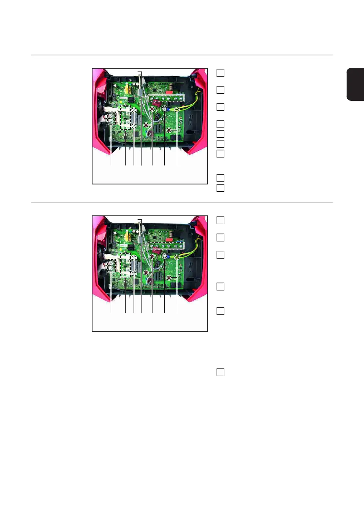
Replacing the BPS1800 PC board
Removing the
BPS1800 PC
board
Open the housing as described in the
section "Opening the TP180 housing"
Unplug all connectors and leads from
the BPS1800 PC board
Undo the four M5x16 TX25 screws (1)
on the secondary transformer leads
Undo the fifteen M4x8 TX25 screws (2)
Undo the four M4x13 TX25 screws (3)
Undo the M4x20 spacer (4)
Disconnect the primary transformer
leads by pushing the terminals (5) to-
gether
Remove the BPS1800 PC board
Clean the heat sink
Installing the
BPS1800 PC
board
Remove the blister cover from the mo-
dules
Align the new BPS1800 PC board and
place it on the cleaned heat sink
Fit four M4x13 TX20 screws (3):
Pretighten at 0.9 Nm
Final tightening torque = 1.8 Nm
Fit the M4x20 spacer (4)
Tightening torque= 1.5 Nm
Fit 15 M4x8 TX20 screws (2)
IMPORTANT! Observe assembly se-
quence (A) ==> (B) ==> (C)!
Pretighten screws at 0.5 Nm
Final tightening torque = 1.5 Nm
Secure the transformer leads with four
M5x16 TX25 screws (1)
Tightening torque = 3.0 Nm
(1) (2)
(1)
(5)
(2) (3)
(3)
(2,4)
1
2
3
4
5
6
7
8
9
(1) (2)
(A)
(1)
(5)
(2)
(B)
(3)
(3)
(2,4)
(C)
IMPORTANT! Route the transformer lead
as shown in the illustration, otherwise faults
may occur.
1
2
3
4
5
6