97
EN
The value set for G-H only applies if the maximum welding current actually has been set.
The actual value is derived from the present welding current. For a medium welding cur-
rent, for example, the actual value will be half of the value set for G-H.
IMPORTANT! The values set for the G-L and G-H set-up parameters are added together.
For example, if both welding parameters are at maximum (25 s / 40 s), the gas post-flow
will last:
- 25 s at minimum welding current
- 65 s at maximum welding current
- 37.5 s if the welding current is exactly half the maximum, etc.
If Aut is set, the gas post-flow time G-H is calculated automatically. This takes the select-
ed process (AC or DC welding) into account.
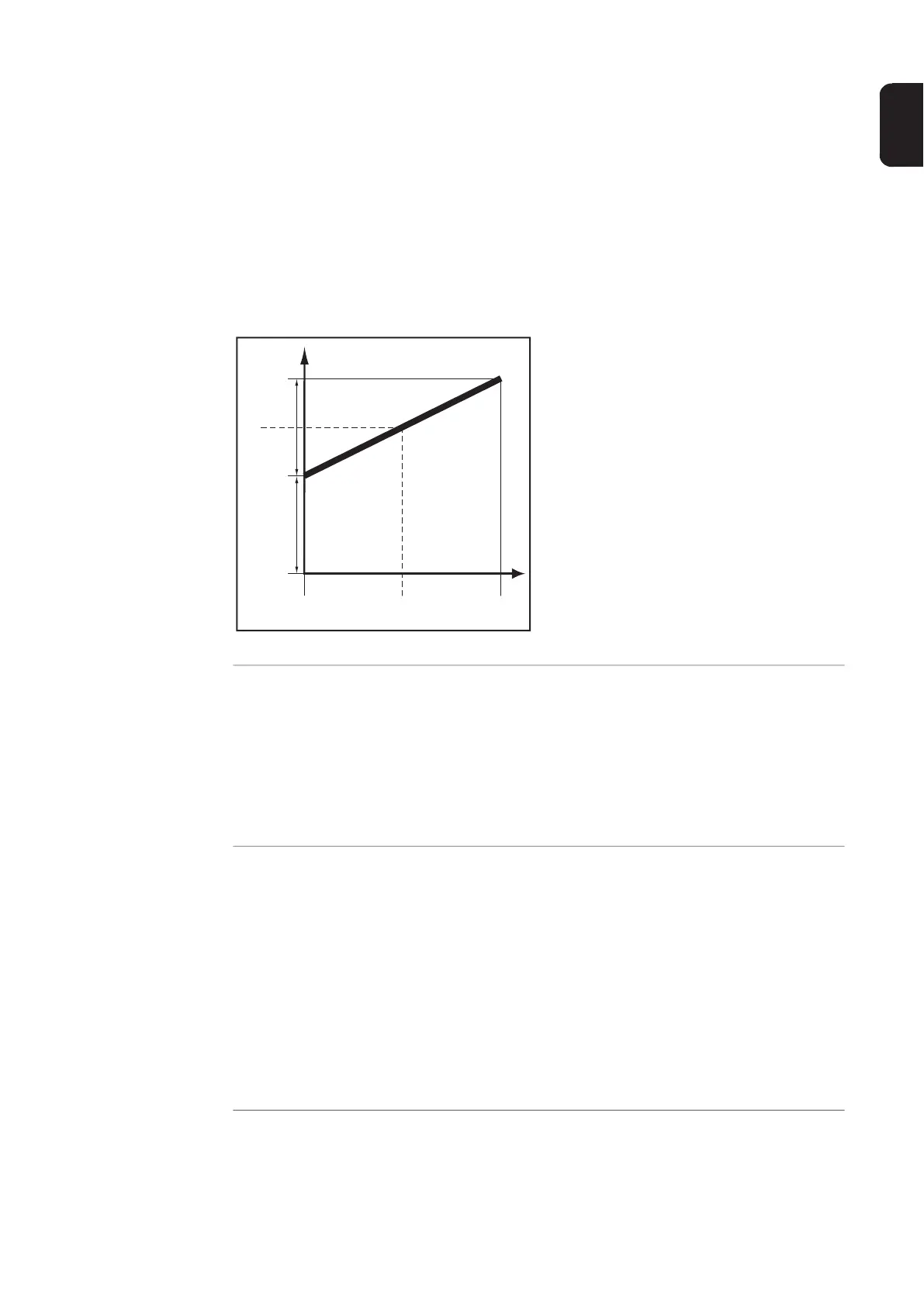
Legend:
(1).... Gas post-flow time at any given mo-
ment
(2).... Welding current at any given mo-
ment
G-H.... Post-flow lmax
G-L .... Post-flow lmin
Gas post-flow time as a function of the welding current
GAS
Gasflow - set value for protective gas shield flow ("digital gas control" option)
Unit l/min cfh
Setting range OFF / 5.0 - max. OFF / 10.71 - max.
Factory setting 15 32.14
IMPORTANT! Please refer to "Digital Gas Control" instructions for more detailed expla-
nations of "GAS" parameters.
GPU
Gas purger - protective gas shield purging
Unit min
Setting range OFF / 0.1 - 10.0
Factory setting OFF
Purging of the protective gas shield begins as soon as a value is set for GPU.
For safety reasons, purging of the protective gas shield cannot be restarted until a new
GPU value is entered.
IMPORTANT! Purging of the protective gas shield is necessary if condensation forms
when the device is left unused in a cold environment for a prolonged period. Long hose-
packs are most affected.
 Loading...