Do you have a question about the FrSky Ethos and is the answer not in the manual?
Create, select, add, clone, or delete models.
Edit basic model parameters like name or picture. Resets mixers if type changes.
Set up switch-selectable tasks or flight behavior. Supports independent trims and mixer variables.
Configure model's control functions, combine inputs, map to output channels.
Interface for adapting logical outputs to mechanical characteristics. Configure throws, reverse, subtrim.
8-character ID for receiver registration and Smart Share. Must be same across transmitters.
Overview of TD-ISRM module: 2.4GHz/900MHz paths, ACCESS, ACCST D16, TD MODE.
2.4G/900M paths work together, supporting up to 3 receivers.
Register receiver to radio. Process involves registration and binding.
Owner/transmitter level ID for Smart Share. Defaults to Owner Registration ID.
Perform range check at field to evaluate reception quality. Reduces transmitter power.
Determine receiver action when transmitter signal is lost (Hold, Custom, No Pulses, Receiver).
Bind a second receiver for redundancy. Connect via SBUS Out to main receiver.
Access receiver options like Telemetry Power, PWM Speed, Port, Share, Reset Bind.
Unique ID for Model Match binding. Sent to receiver during binding.
Initiate binding process for ACCST D16. Select operation mode (Telemetry/Channels).
Receiver Signal Strength Indicator. Warns of low signal quality.
Valid Frame Rate sensor for Link Quality. Can set up alerts via Logical Switches.
Enable to discover new sensors after connection and binding. Flashing dot indicates data reception.
Add a DIY or 3rd party sensor. Configure Name, Value, Unit, Decimals, Range, etc.
List detected S.Port/F.Port sensors. Select DIY sensor from list. Auto-populates IDs.
Add calculated sensors like Consumption, Distance, and Trip.
Calculate energy consumed by motor from current sensor (e.g., FAS series). Configure Name, Unit, Range.
Calculate distance traveled from GPS sensor. Configure Name, Unit, Range (0-10km).
Calculate accumulated distance between GPS coordinates. Configure Name, Unit, Range (0-10km).
Edit sensor settings: Value, ID, Name, Unit, Decimals, Range, Write Logs.
Reset flight data, timers, or telemetry values. Configure Active Condition.
Set failsafe for internal module. Function under construction at time of writing.
Initial steps for setting up the radio itself before programming models.
Throttle safety latching mechanism. Prevents unexpected motor start.
Cut motor in emergency. Instantly reduces throttle output to -100%.
Monitor battery voltage with FLVSS sensor, set alert threshold using Logical Switch.
Monitor battery usage (mAh) with Neuron ESC, set warning for consumption or voltage.
Use FASxxx current sensor with calculated Consumption sensor for battery monitoring.
Add Butterfly mix for glider braking. Use curve to convert slider range, set aileron/flap response.
| Operating System | ETHOS |
|---|---|
| Telemetry | Yes |
| Voice Alerts | Yes |
| Haptic Feedback | Yes |
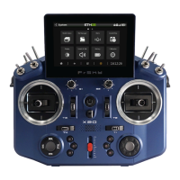
| Screen | Color Touch Screen Display |
| Battery | Lithium Battery |
| Compatibility | FrSky Receivers |
| User Interface | Touch screen based |
| Updates | Firmware updates via USB or SD card |
| Customization | Highly customizable |
| Model Memory | Supports multiple model profiles |