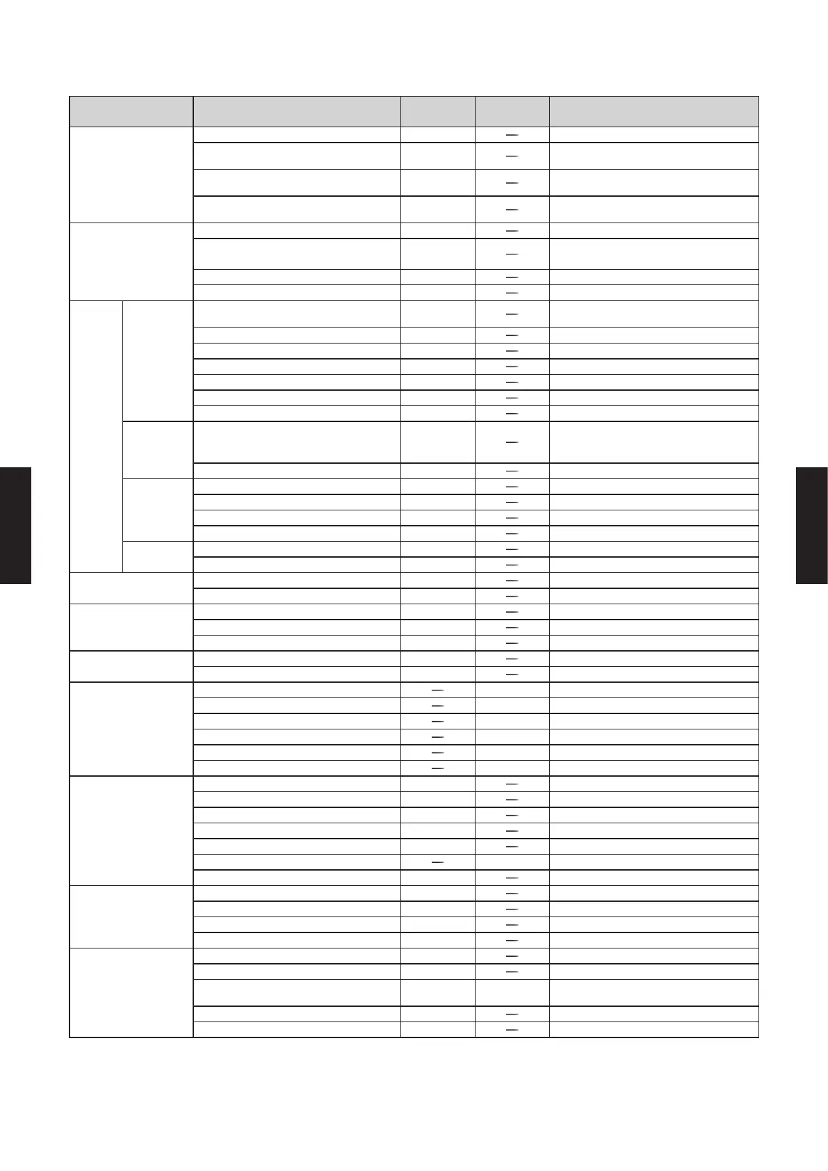
SPECIFICATION SUMMARY
Type Function UTY-APGX
UTY-PEGX
*1 Option
Remark
System specication
Max. System Controller per VRF Network 1
Max. VRF networks supported 4
Site with up to 4 VRF networks may be
administered with 1 System Controller
Max. indoor units / remote controller groups
per VRF network
400
Max. indoor units / remote controller groups
per System Controller
1,600 4 VRF networks
Site supervision
Multiple sites display 10
2D/3D graphical layout view
z
2D: Site, oor, 3D: Building
Quick control from display available.
List display
z
Quick control from display available.
Tree display
z
Quick control from display available.
Operation
control
Individual
Start/Stop, Operation mode, Room
temperature
z
Fan speed, Airow direction
z
Economy mode
z
Antifreeze
z
Remote control prohibition setting
z
Temperature upper and lower limit setting
z
Filter sign reset
z
Schedule
Annual schedule
z
Week of year, day of month, day of week
setting.
Holiday special day settings.
Low noise mode weekly schedule
z
Outdoor unit control only.
Group
management
Number of groups 1,600
Group in group 3 Levels Lv.1 – 2 – 3.
Max. overlap denitions 1,600 1 unit may belong to up to 1,600 groups.
Auto generation
z
By site, building and oor.
Others
Memory operation
z
Operation pattern memorized and reused.
Pattern operation
z
Reuse operation pattern once used.
Operation status
monitoring
Controlled status
z
See items controlled by operation.
Special operation
z
Defrost, Oil Recovery.
Error management
Error notication
z
Audible alarm
z
Error e-mail notication
z
History management
Error history 1 year
Operation control & status history 1 year
Energy saving
management
Indoor unit rotation
z
Outdoor unit capacity save
z
Peak cut control 1 month
Input power monitor
z
Electricity meters supported 200 Outdoor unit required per connection
Input power information 3 years
Electricity charge
apportionment
Apportionment charge calculation
z
Apportionment charge bill creation
z
Tenant (block) setting 1,600
Common facilities apportionment setting
z
Rated input power allotment setting
z
Electricity meters supported 200 Same meters used for energy saving.
Electricity charge apportionment period 2 years
Remote control
Internet, telephone line support
z
Max. client connection per server 5
Max. host connection from client 10
Data encryption
z
SSL used.
Others
User control
z
Authorization level setting.
Database import / export
z
Multiple language display
z z
English, Chinese, French, German, Spanish,
Russian, Polish.
Floor layout editor
z
Floor layout import/export
z
The electricity charge apportionment function of VRF system can only be performed from one equipment simul-
taneously.
- (05 - 22) -
CONTROL
SYSTEM
CONTROL
SYSTEM

 Loading...


