1-7. INDOOR UNIT CONNECTION CHECK
This function is available J-II series.
NOTE
● It is necessary to stop SERVICE TOOL (UTY-ASGX) and WEB MONITORING TOOL (UTY-AMGX), when
you will carry out indoor unit connection check.
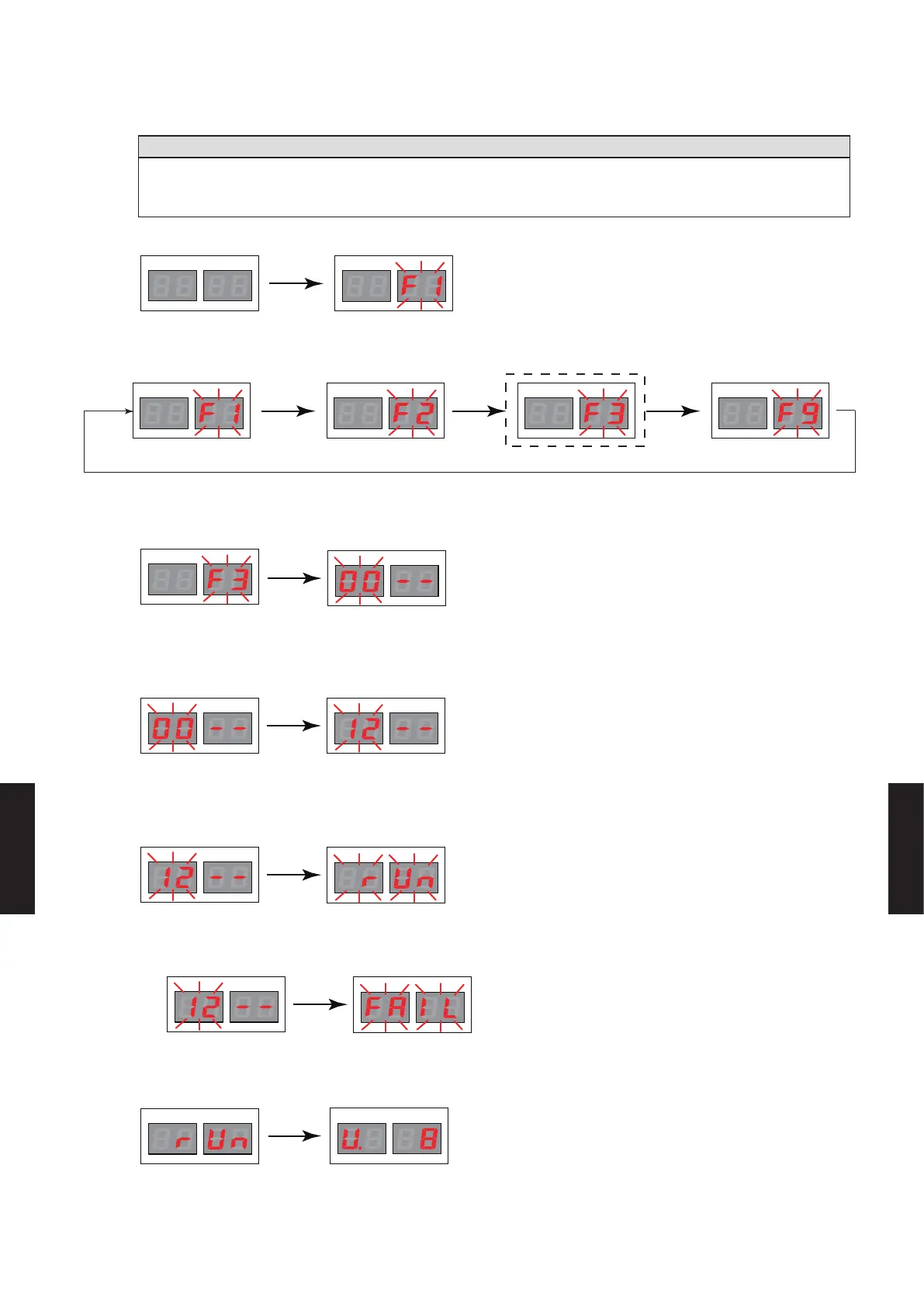
1) After verifying that the system is normally, press the MODE/EXIT button (SW107) once.
LED105 LED104
LED105 LED104
2) Press the SELECT button (SW108) to display “F3” on the LED104.
(The display of the LED104 changes each time the SELECT button is pressed.)
LED105 LED104LED105 LED104 LED105 LED104 LED105 LED104
*1 *1
(Monitoring mode) (Setting mode) (Function mode)
(Error history mode)
*1 : The “F1” and “F9” modes are used for maintenance, so do not set them in regular
3) When “F3” appears on the LED104, press the ENTER button (SW109).
LED105 LED104
LED105 LED104
A ashing display appears on the LED105.
4) Press the SELECT button (SW108) to display “12” on the LED105.
LED105 LED104
LED105 LED104
5) When “12” appears on the LED105, hold down the ENTER button (SW109) for at least 3
seconds. (Unless it is held down for at least 3 seconds, the selection will not be conrmed.)
When the Indoor Unit Connection Check function is activated, the display changes to “run”.
LED105 LED104
LED105 LED104
● When the Indoor Unit Connection Check function is not activated (during maintenance), the
display changes to “FAIL”.
6) When Indoor Unit Connection Check is completed, the number of indoor unit is displayed on
the LED104, LED105. Verify that the count matches the number of indoor units being installed.
LED105 LED104
LED105 LED104
Ex.) When eight indoor units are being connected
LED105 LED104
LED105 LED104
- (07 - 56) -
FUNCTION
SETTING
FUNCTION
SETTING

 Loading...


