2-8-2. MODEL: UTY-RHKU
● Easy operation.
● Built-in Backgroud Light function.
● Easy installation with a slim shape with no bulge in the back.
● Error history. (Last 16 error codes can be accessed.)
● Up to 16 indoor units can be simultaneously controlled.
● Can be installed onto SW-BOX. (applies to European and other
country's standard)
● Concentrates on the basic operations such as Start/Stop, Fan
Control, and Temperature Setting.
This controller cannot select mode. An additional controller
is required for the user to select heating or cooling mode.
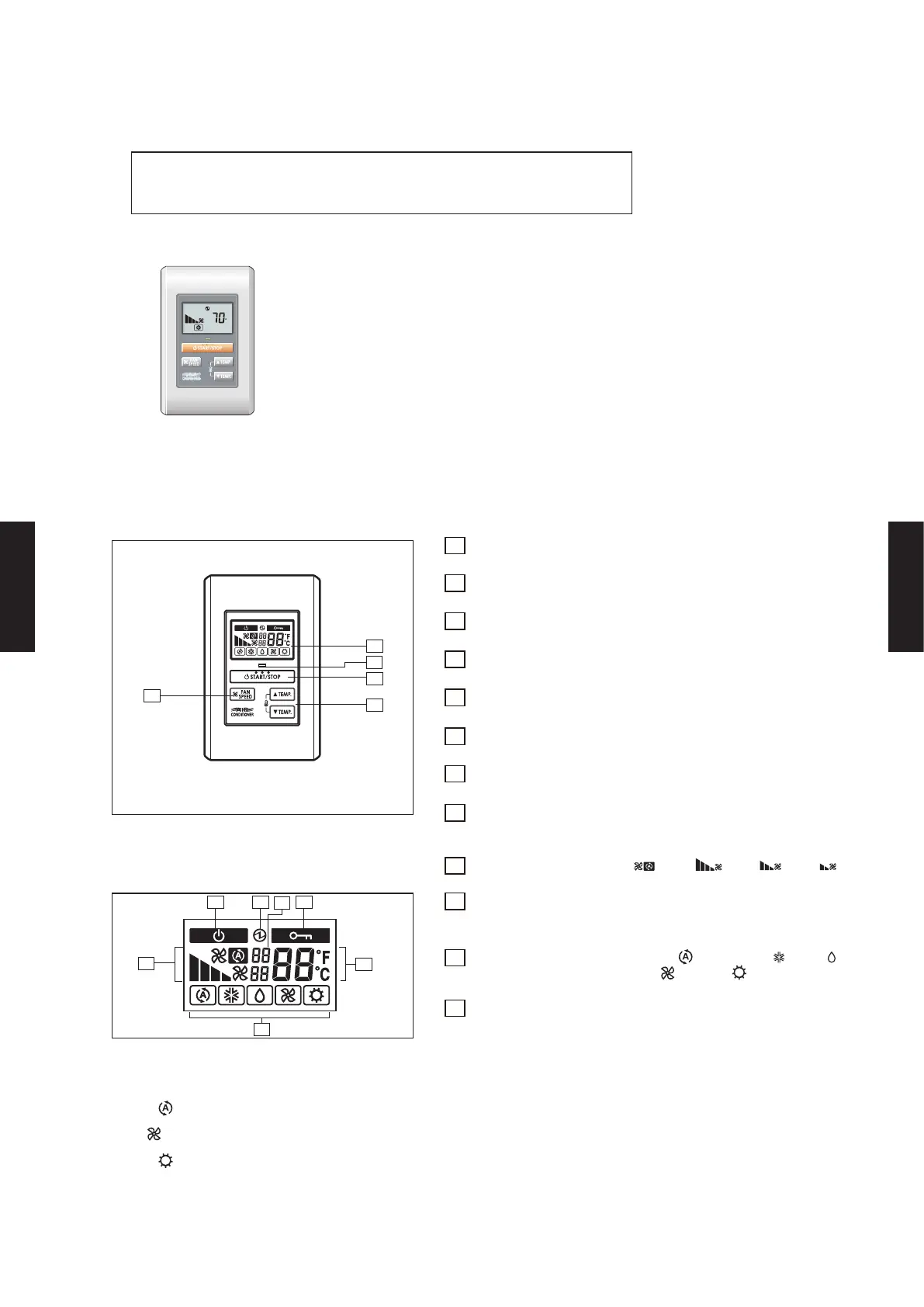
1 START/STOP button
Pressed to start and stop operation.
2 Display with backlight
Lights during operation.
3 Operation lamp
Lights during operation.
4 Fan control button
Selects the fan speed
5 Set temperature button
Selects the setting temperature.
6 Standby display
Indicates during the oil recovery and defrosting operation.
7 Power source display
Indicates the main power ON.
8 Central control display
Indicates when function is locked from Display with backlight Touch
Panel Controller or System Controller.
9 Fan speed display
(AUTO
, HIGH
, MED
, LOW
).
10 Set temperature
Indicates Error history number. *1
Indicates Indoor unit address. *2
11 Operating mode display
(AUTO
*
1, COOL
, DRY
,
FAN
*
2, HEAT
*
3).
12 (Upper) Indicates the error code *1, *3
/ the refrigerant
system address. *2
(Lower) Indicates the remote controller address. *1, *2, *3
FUNCTIONS
Display panel
*1 : "AUTO " is not available for a heat pump model unless it is set up master indoor unit.
*2 : "FAN " is not available for a heat pump model
*3 : "HEAT " is not available for a cooling only model
*4 : during Error code history display mode.
*5 :
during address display mode.
*6 :
during self Diagnosis mode.
F
5
4
1
2
3
6
7
8
9
10
11
12
- (05 - 83) -
CONTROL
SYSTEM
CONTROL
SYSTEM

 Loading...


