2. FUNCTION SETTING
2-1. OUTDOOR UNIT
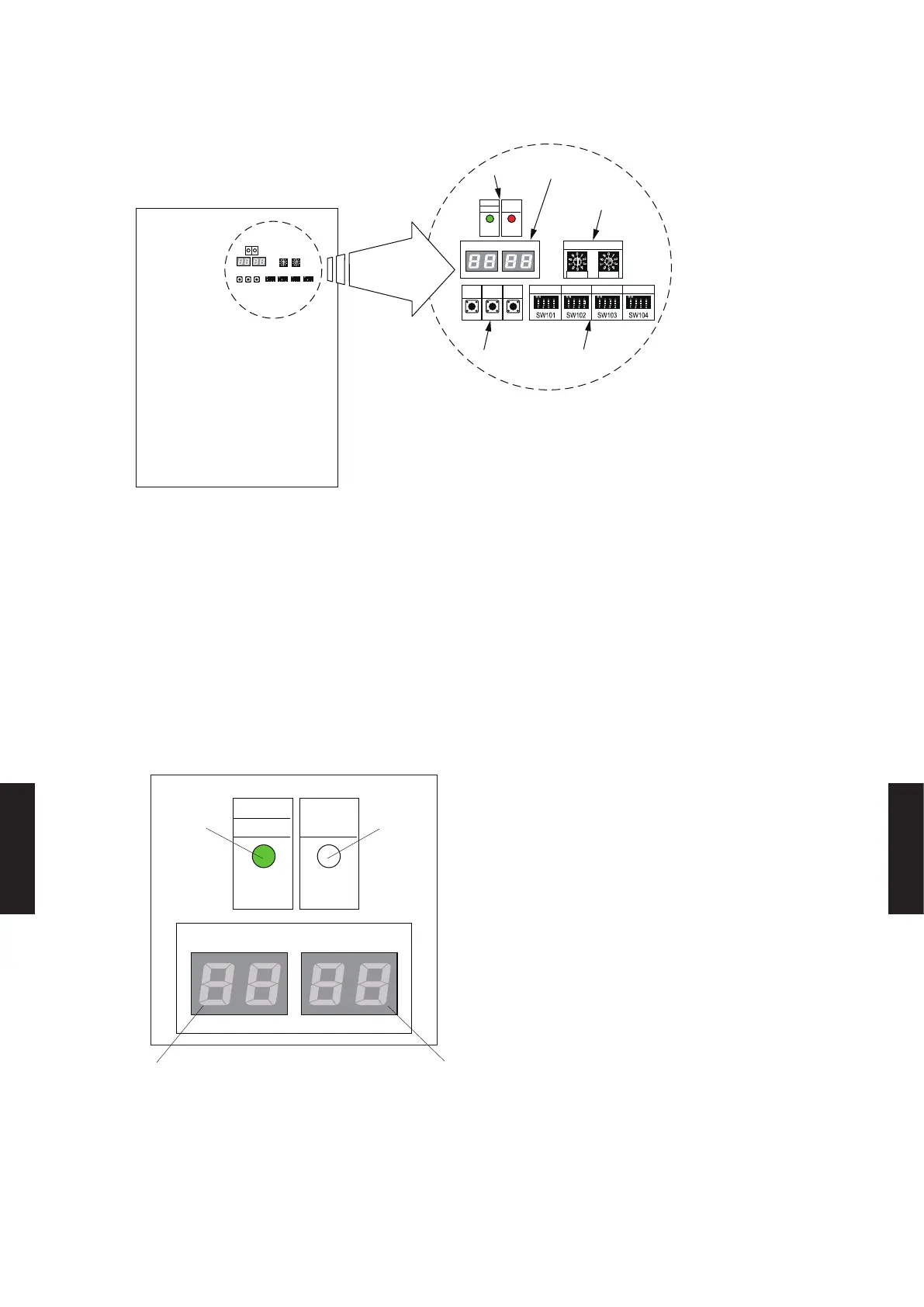
SWITCH POSITION
LED101
(GREEN)
SW107 SW108 SW109
SW106 SW105
POWER
MODE
MODE
/EXIT
LED105 LED104
REF AD
SET1 SET2 SET3 SET4
LED102
(RED)
ERROR
SELECT ENTER
X 10 X 1
Outdoor unit printed circuit board
LED lamp
7 Segment
LED Lamp
Rotary switch
DIP switch
Push button
● Set the functions of an outdoor unit with the push buttons (SW107, SW108 and SW109) while observing the
7-segment LED lamps (LED105 and LED104) on the printed circuit board.
PREPARATION
1) Be sure to check that the operation of the outdoor unit has stopped (be sure to stop the
operation if it is still running), and turn o the power.
2) Remove the front panel of the outdoor unit, and remove the lid of the electrical component box
in order to expose the printed circuit board.
3) Turn on the power of the outdoor unit.
LED101
(GREEN)
POWER
MODE
LED105 LED104
LED102
(RED)
ERROR
When the system is normal
(O)
(On) (O)
(O)
● As shown in the above figure, make sure that the POWER/MODE indicator lamp (LED101) is on and the ERROR
indicator lamp (LED102) is off.
● If the ERROR indicator lamp (LED102) flashes, it indicates that an error has occurred. Check wiring and power
supply. After making sure that the ERROR indicator lamp (LED102) has turned off, proceed to the next step.
- (07 - 58) -
FUNCTION
SETTING
FUNCTION
SETTING

 Loading...


