z
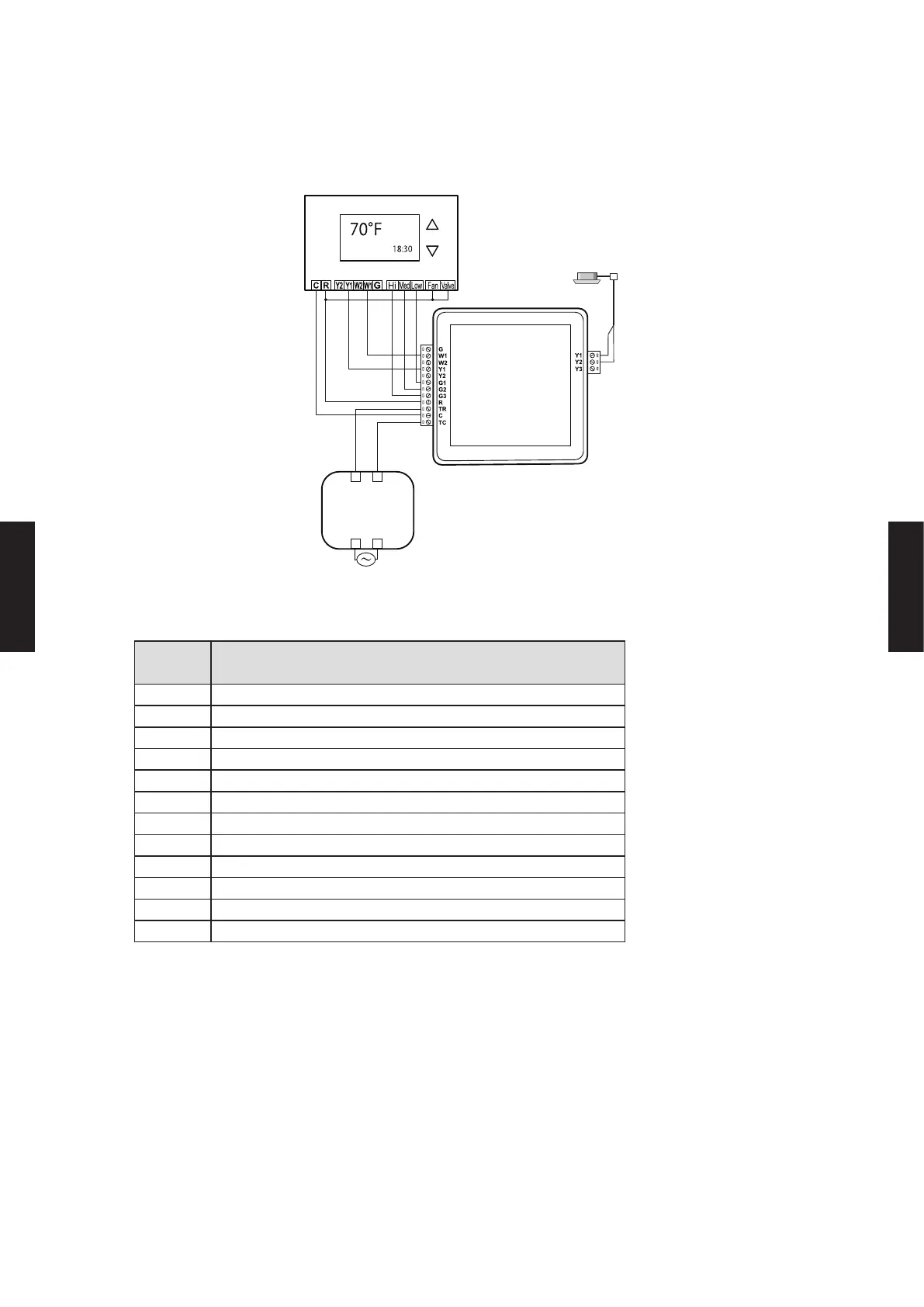
Single-stage Cooling and Heating with Dedicated Fan speed Relays
Example: Remote controller for 2-wire type
(Locally purchased)
AC 208/230 V
AC 24 V
AC 24 V
Max.
16 units
Indoor unit
Thermostat convertor
Thermostat
controller
Transformer*
Fan
Install the transformer, as necessary, per building code and manufacturer’s
installation instructions. Maximum Power: 5.0 VA
*
Terminal
name
Application
TC Common (In) from transformer
C Common to the thermostat controller
TR Power supply from transformer
R Power supply to thermostat controller
G3 Airow High
G2 Airow Medium
G1 Airow Low
Y2 Cooling stage 2
Y1 Cooling stage 1
W2 Heating stage 2
W1 Heating stage 1
G Fan
NOTES:
● For remote controller cable, 2-wire type and 3-wire type are available depending on the device to be
connected.
● All wiring shown should be performed with 18 AWG thermostat wire.
● Terminals to thermostat controller on Thermostat convertor support AC 20 to 30 V.
● HIGH/MEDIUM/LOW fan signals are optional, and may not be available on all thermostat controllers.
● Signals for stage 2 are optional. W2 and Y2 terminals may not be used in single-stage thermostats. To use the
stage 2 signals, turn on the DIP switch SET3-1 on each convertor.
● Up to 16 indoor units be controlled with a single thermostat controller. Multiple indoor units connected to one
thermostat convertor are operable by the same operating setting.
● Two or more types of VRF system, single model, or multi systems cannot be mixed together.
- (05 - 149) -
CONTROL
SYSTEM
CONTROL
SYSTEM

 Loading...


