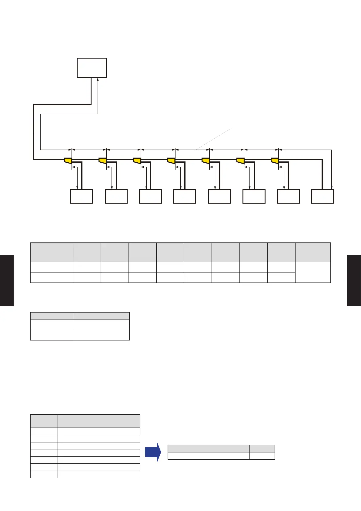
2-6. EXAMPLE OF PIPING DESIGN
REFRIGERANT SYSTEM 1
b
a
a1 b1 c1 d1 e1 f1 g1
c d e f g h
1 2 3 4 5 6 7 8
BP1 BP2 BP3 BP4 BP5 BP6 BP7
Outdoor
unit
Indoor
unit
(62.0kBtu/h)
(52.5kBtu/h)
(45.0kBtu/h)
(37. 5k Btu / h)(30.0kBtu/h)
(22.5kBtu/h)
(15.0kBtu/h)
(9.5kBtu/h) (7.5kBtu/h)
(7. 5 k Btu / h)
Indoor
unit
Indoor
unit
Indoor
unit
Indoor
unit
Indoor
unit
Indoor
unit
Total cooling capacity of indoor units
connected downwards to the pipe.
Indoor
unit
z
System conguration
(Indoor units)
1 2 3 4 5 6 7 8
Total
Capacity
(Btu/h)
Model name ARUL09 ARUL07 ARUL07 ARUL07 ARUL07 ARUL07 ARUL07 ARUL07
62,000
Capacity (Btu/h) 9,500 7, 50 0 7, 5 0 0 7,5 0 0 7,5 0 0 7,5 0 0 7,5 0 0 7, 5 0 0
z
System conguration
(Outdoor unit)
Outdoor unit
Model name AOU60
Capacity (Btu/h) 60,000
z
Capacity ratio
(Total indoor unit capacity) / (Total outdoor unit capacity)
= (62,000) / (60,000) = 103.3% (Within 50% to 130%)
z
Selection of branch kit
Branch
point No.
Model
BP1 UTP-AX090A
BP2 UTP-AX090A
BP3 UTP-AX090A
BP4 UTP-AX090A
BP5 UTP-AX090A
BP6 UTP-AX090A
BP7 UTP-AX090A
Model Q'ty
UTP-AX090A 7
(7.5kBtu/h) (7.5kBtu/h) (7.5kBtu/h) (7.5kBtu/h) (7.5kBtu/h) (7.5kBtu/h)
- (06 - 22) -
SYSTEM
DESIGN
SYSTEM
DESIGN

 Loading...


