1. EXTERNAL INPUT & OUTPUT
Note :
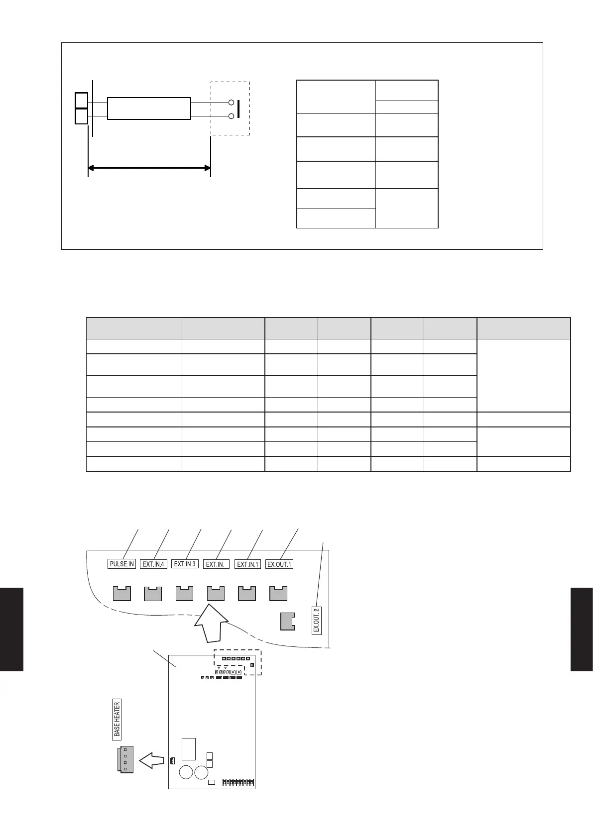
The length regulations of the cable are as shown in the following gures.
1
2
connected unit
Max. Length = L
cable
P.C. B
Type
L (m)
[ft. (m)]
Input / Output
Outdoor unit
492 / 492
(150 / 150)
Indoor unit
492 / 82
(150 / 25)
RB unit
150 / -
(492 / -)
Touch Panel
Controller
82 / 82
(25 / 25)
Central Remote
Controller
1-1. OUTDOOR UNIT
External input External output Connector VR-II V-II J-II External connect kit
(Optional parts)
Low noise mode -
CN131
○ ○ ○
UT Y-XWZXZ6
Cooling/Heating
priority
- CN132
○ ○
Outdoor unit operation
peak control
- CN133
○ ○ ○
Emergency/batch stop -
CN134
○ ○ ○
Electricity meter pulse -
CN135
○ ○ ○
UT Y-XWZXZF
- Error status
CN136
○ ○ ○
UT Y-XWZXZ6
- Operation status
CN137
○ ○ ○
- Base heater
CN115
○ ○ ○
UT Y-XWZXZ9
TERMINAL POSITION
z
VR-II series and V-II (460V) series
*1: Input 2 Terminal(CN132) is not in VR-II series.
Input 4 Input 3 Input 1 Output 1Input 5 Input 2
*1
CN135
(ORANGE)
Outdoor unit PCB
CN131
(YELLOW)
CN132
(GREEN)
CN136
(BLACK)
CN137
(BLUE)
CN134
(RED)
CN115
(BLACK)
CN133
(WHITE)
Output 2
2
- (08 - 01) -
EXTERNAL INPUT
& OUTPUT
EXTERNAL INPUT
& OUTPUT

 Loading...


