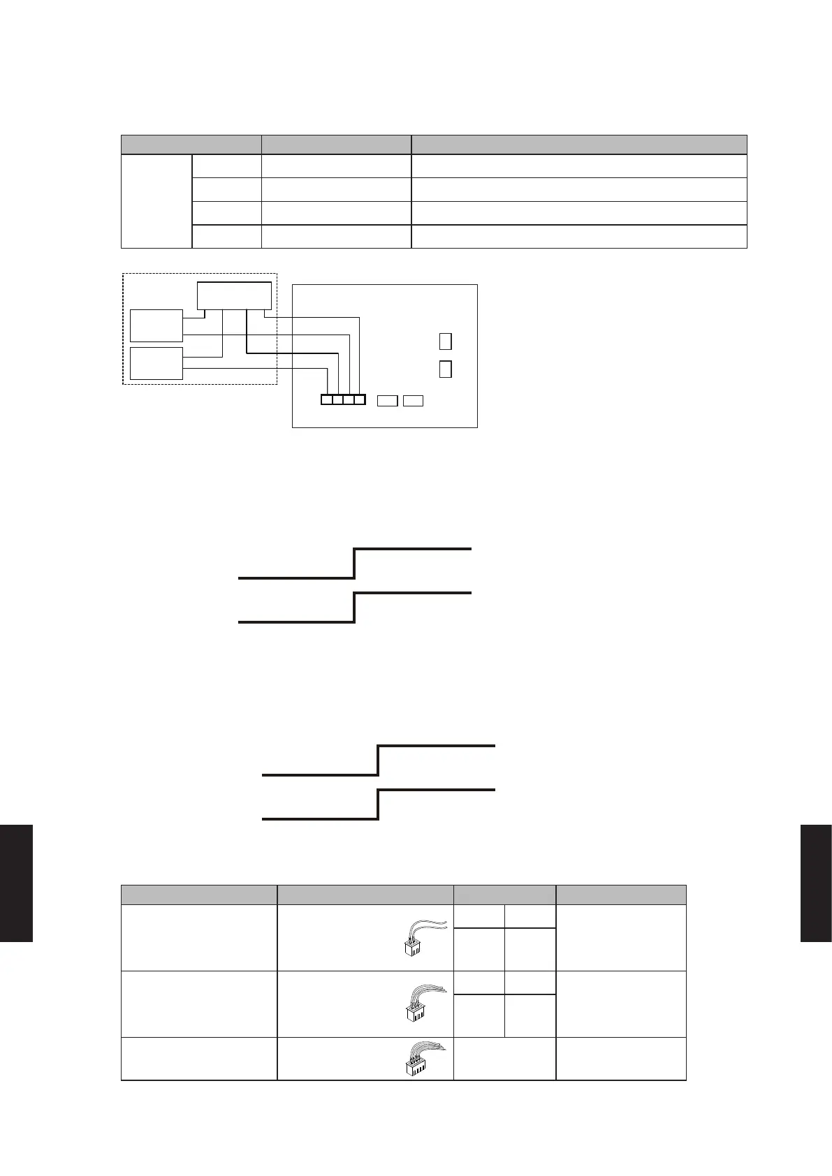
1-5-2. EXTERNAL OUTPUT
Connector Output voltage Status
CN9
(Black)
Ch1 0 V All of indoor units "Stop"
Pins3-4 DC 12 V *5 At least one more indoor units "Operation"
Ch2 0 V Normal
Pins1-2 DC 12 V *5 Error
*5: Provide a DC12 V power supply. Select
a power supply capacity with an ample
surplus for the connected load.
Do not impress a voltage exceeding 12 V
across pins 1-2, and 3-4
*6: The allowable current is DC 15 mA or
less. Provide a load resistance such that
the current becomes DC 15 mA or less.
*7: Polarity is [+] for pins 1,3 and [-] for pins
2,4.
CN9
PCB
1
3
4
+
+
+
+
-
-
-
-
*7)
2
DC power
supply 12 V
Connect-
ed load *6
Connect-
ed load *6
Connected unit
OPERATION STATUS (External output1)
The output for CN9 (3-4) is ON when at least one more indoor units is operating.
The output is OFF when all of indoor units is stopped.
CN9 (3-4)
Output
Indoor
units
Operation
Stop
12 V
0 V
ERROR STATUS (External output2)
The output for CN9 (1-2) is ON when Error of at least one more indoor unit or outdoor unit or
Central remote controller is generated.
CN9 (1-2)
Output
Indoor unit or
Outdoor unit or
Central remote
controller
Error
Normal
12 V
0 V
1-5-3. PARTS
Usage Name and shapes Q'ty Models
For control input port
(Dry contact terminal)
External
CONNECT KIT
Edge Pulse
UTY-XWZ X Z7
1 2
For control input port
(Apply voltage terminal)
External
CONNECT KIT
Edge Pulse
UTY-XWZ X Z8
1 2
For output port
External
CONNECT KIT
1 UTY-XWZXZA
- (08 - 56) -
EXTERNAL INPUT
& OUTPUT
EXTERNAL INPUT
& OUTPUT

 Loading...


