33
< BeforeUse >
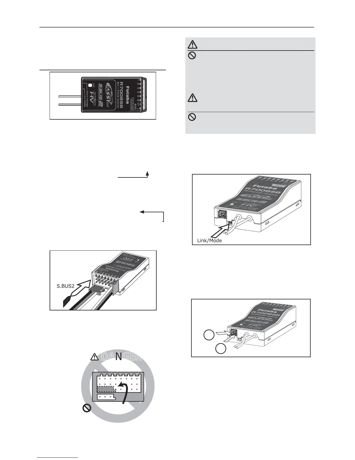
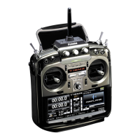
Link/Mode Switch
Use the small plastic screw driver that was
included with your receiver.
The Link/Mode Switch is also used for the CH
mode selection.
Extra Voltage Connector
Use this connector when using a voltage
telemetry device to send the battery voltage (DC0
~ 70V) from the receiver to the transmitter.
You will need to purchase the optional External
Voltage input cable (CA-RVIN-700) FUTM5551.
You can then make a cable with an extra
connector to the External voltage connector.
Before using the receiver, be sure to read the
precautions listed in the following pages.
ŵƈƆƈƌƙƈƕŃŵŚœœśŶť
Connector
"1 through 6": outputs for the channels 1
through 6
"7/B": outputs of 7 channels and power.
"8/SB": outputs of 8 channels or S.BUS port.
[S.BUS Servo S.BUS Gyro ]
*When using 8/SB as S.BUS, you have to set
CH MODE of the following page to mode B or
mode D.
"S.BUS2": outputs of S.BUS2 port.
[S.BUS2 Servo S.BUS2 Gyro Telemetry Sensor ]
*When using 9 or more channels, use an S.BUS
function or use a second R7008SB and link both
to your transmitter.
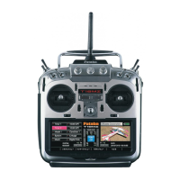
Connector insertion
Firmly insert the connector in the direction
VKRZQLQWKH¿JXUH,QVHUWWKH6%86E\WXUQLQJ
it 90 degrees.
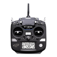
+
−
Do not connect either a switch
or battery in this manner.
5HFHLYHU
DANGER
DANGER
Don'tattachaconnectorasshownin
theprecedingillustration.
*Itwillshort-circuitifconnectedinthisway.A
shortcircuitacrossthebatteryterminalsmay
causeabnormalheating,fireandburns.
WARNING
S.BUS2connectors
Don'tconnectanS.BUSservo/gyro
toS.BUS2connector.
LED Monitor
This monitor is used to check the CH mode of
the receiver.
ŵƈƆƈƌƙƈƕŃƑƒƐƈƑƆƏƄƗƘƕƈ