4-48 250 Series Maternal/Fetal Monitor Revision D
2020551-001
Maintenance: J102 Analog Output Connector DAC Static Test
Main Board SW1 Switch Settings
This area of the display allows you to see the hardware switch settings (SW1) on the
Main Motherboard—without removing the cover of the monitor. The switch settings
are displayed from left (SW1-8) to right (SW1-1). Refer to Table 17.
To access the Diagnostic Control screen select the Service softkey at the bottom of the
General Setup Screen. Input the Service Lock access code, then the Install Options
Screen 1 appears. Select the Te s t s softkey from the bottom of the screen, the
Diagnostic Control screen appears.
Example 1:
1 0 1 0 1 1 1 0
MECG MSpO2 NIBP
J102 Analog Output Connector DAC Static Test
This screen displays the
J102
pin numbers, the signal descriptions, the range of
allowable values for measured voltages, the expected output voltages, and the settings
(meaning) adjustable using the Trim Knob control. Use this screen while verifying and
calibrating the digital-to-analog converters (DACs) on the Communications Board (No.
13388 or 15297).
1. Access the Diagnostic Control screen by selecting the Service softkey at the
bottom of the General Setup Screen. Input the Service Lock access code, then the
Install Options Screen 1 appears. Select the Te s ts softkey from the bottom of the
screen. (Refer to“Diagnostic Control Screen” on page 5-5 for instructions.)
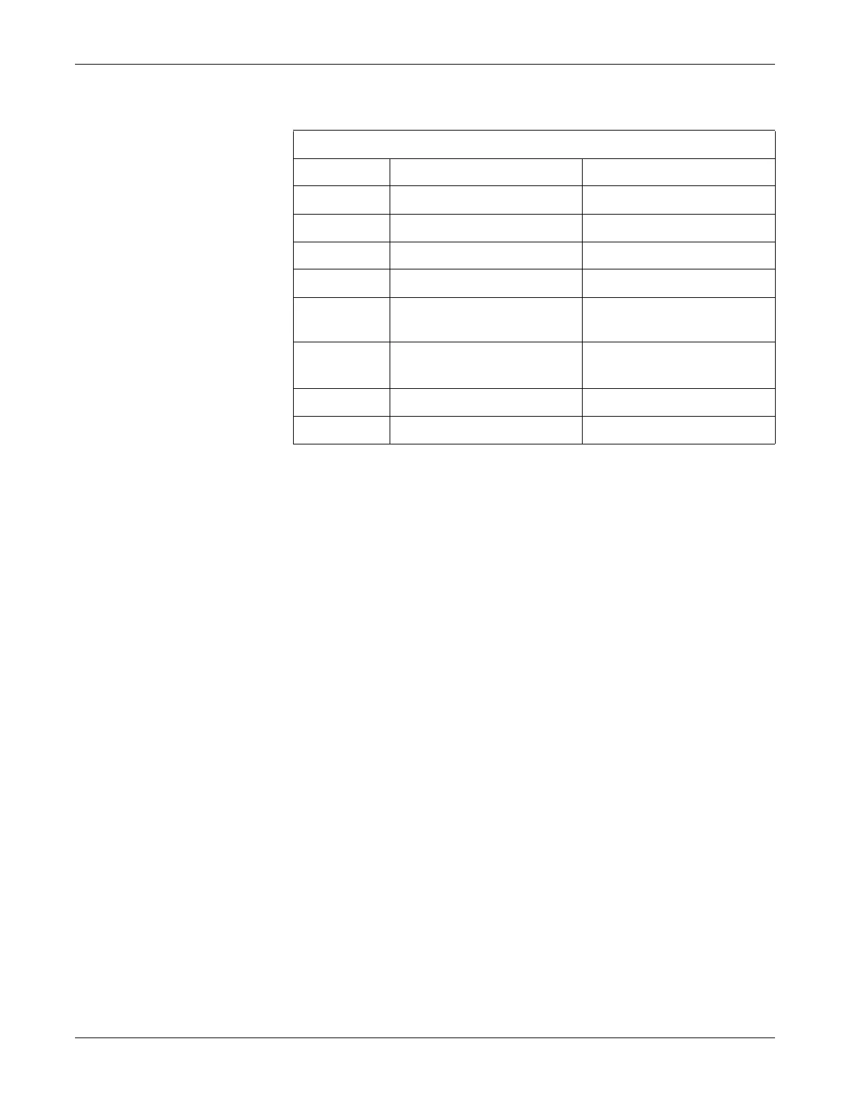
Table 16. Hardware Switch Settings
Switch # Description Setting
1 Factory Test Off = Enabled
2 J102 Output Levels Off = HP, On = Coro
3 Reserved Set to Off
4 NIBP Option Off = Enabled
5MSpO
2
Option 5:Off 6:Off = Nellcor
5:Off 6:On = Ohmeda
6MSpO
2
Option 5:On 6:Off = Masimo
5:On 6:On = No MSpO
2
7 Inactive Inactive
8 MECG Option Off = Enabled

 Loading...


