4-54 250 Series Maternal/Fetal Monitor Revision D
2020551-001
Maintenance: Power Supply Voltages—Verification
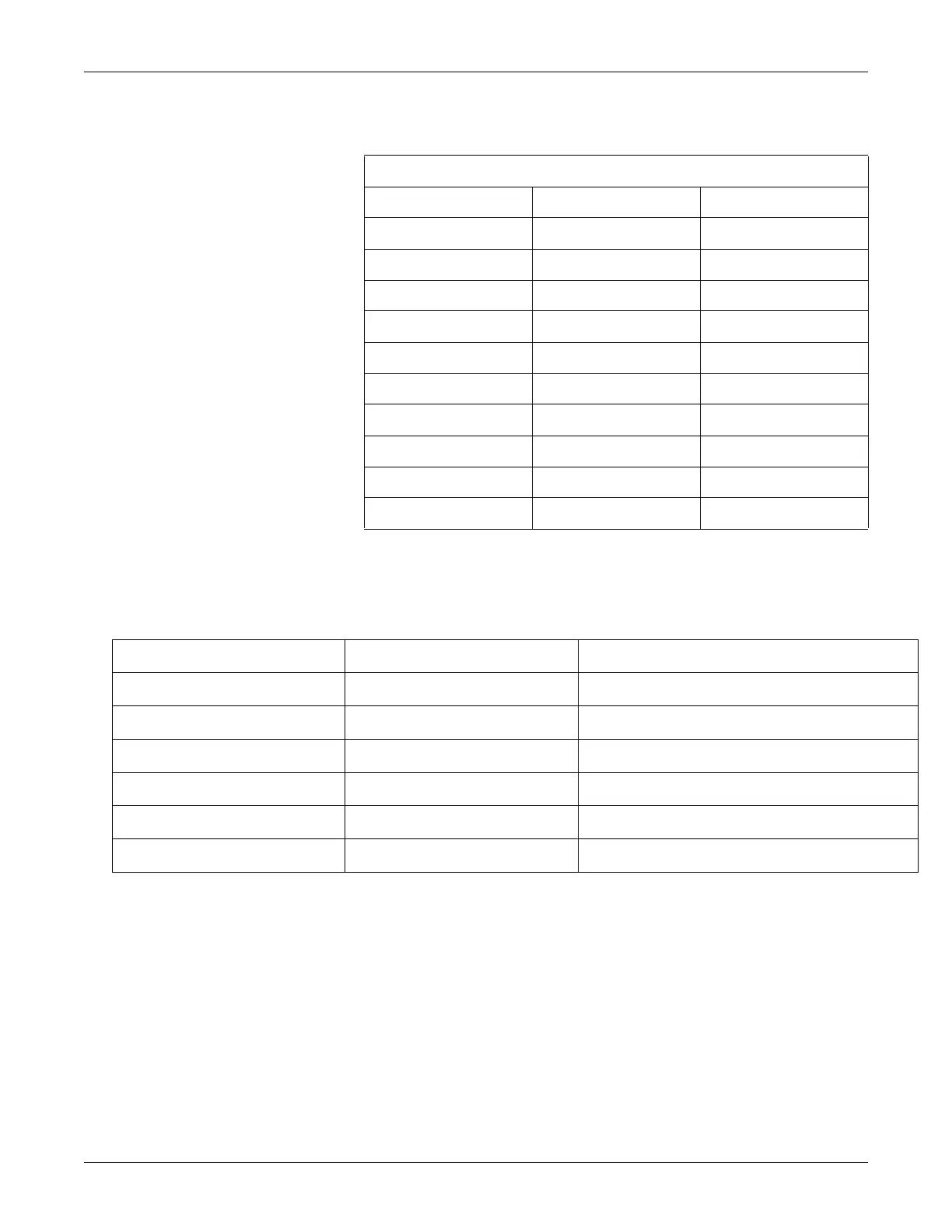
Isolated Power Supply Board Voltages
Verify the following voltages, being sure to use the correct ground reference points.
Isolated FECG/UA Board Voltages
This procedure performs an adjustment on the FECG/UA Board.
Connect the positive lead of a digital voltmeter to TP1 on the FECG/UA Board.
Connect the negative lead to TP2 or TP3 (isolated ground).
Adjust R28 for a reading of +4.00 Vdc ± 0.01 Vdc.
Table 20. Main Board Power Supply Voltages
2023111-001 Signal Name Voltage Level
Pin 1 +12EL +12 Vdc ± 0.5 Vdc
Pin 2 +20I +20 Vdc ± 0.5 Vdc
Pin 3 +15BP +15 Vdc ± 0.5 Vdc
Pin 4 –15V –15 Vdc ± 0.5 Vdc
Pin 5 +15V +15 Vdc ± 0.5 Vdc
Pin 6 +12A +12 Vdc ± 0.5 Vdc
Pin 7 +5V +5 Vdc ± 0.5 Vdc
Pin 8 GND —
Pin 9 No Connection —
Pin 10 Keying —
Ground Reference Test Point Measurement Limit
TP8 TP7 16.5 ±.15 Vdc
TP8 TP17 15 ±.75 Vdc
TP8 TP16 -15 ±.75 Vdc
TP8 TP18 5 ±.25 Vdc
TP5 TP10 15 ±.75 Vdc
TP5 TP11 -15 ±.75 Vdc

 Loading...


