5-10 250 Series Maternal/Fetal Monitor Revision D
2020551-001
Troubleshooting: Diagnostic Control Screen
1. Loosen the four hex-head lock screws—two on each side. The right side screws
are labeled B in the figure on page 5-12.
2. To move the printhead forward on one side, back-off the corresponding captive
screw (turn counterclockwise) from its alignment block. To move the printhead
backward on one side, tighten the corresponding captive screw (turn
clockwise).
3. After making the necessary adjustments, tighten the four hex-head lock screws
labeled B.
Thermal Printhead
The thermal printhead is a part of the printhead assembly. Refer to the parts list in
Chapter 6, “Parts List, Drawings, and Replacement” , of this manual for ordering
information.
Removing the Printhead
Use the following procedure for removing the 250 Series Monitor printhead. As
long as you have a short screwdriver, you will not need to remove the strip chart
recorder from the monitor.
1. Turn off the 250 Series Monitor and disconnect the power cord from the
monitor.
2. Remove the nine screws which secure the monitor top cover. Four screws are
located on the bottom of the monitor and five screws are located in the back.
3. Remove the cover by sliding it toward the rear of the monitor.
4. Disconnect the printhead harness cable from J3 on the Recorder Board.
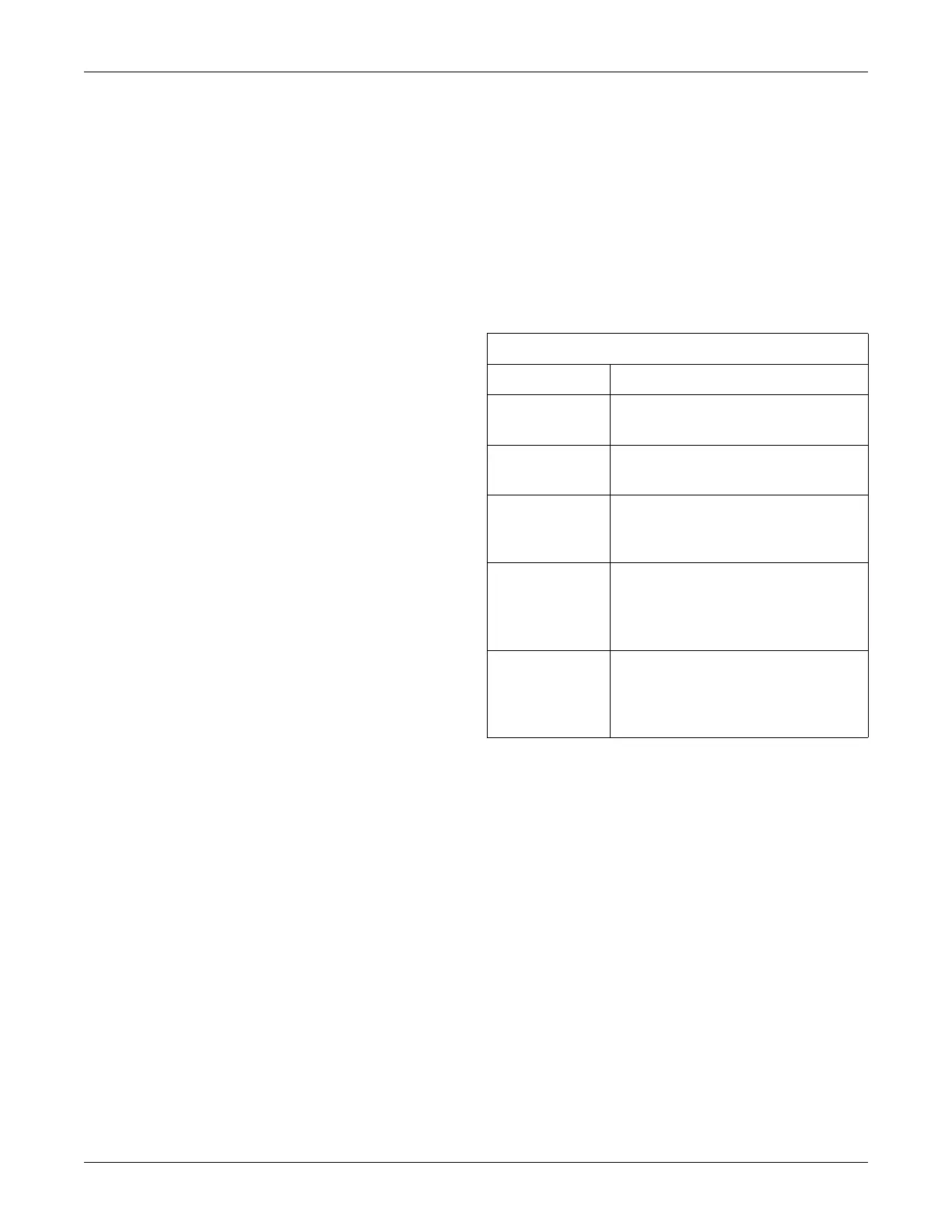
Table 21. Printhead Adjustments
Adjustment Description
A Set screws loosened to perform a vertical
offset adjustment.
B Hex-head screw loosened to perform a
horizontal offset adjustment.
C Hex-head screw which determines the
vertical offset of a horizontal line. (See
Figure on page 5-13.)
D Captive hex-head screw which controls
the horizontal offset of a vertical line on
the top grid of the strip chart paper (heart
rate channel).
E Captive hex-head screw which controls
the horizontal offset of a vertical line on
the bottom grid of the strip chart paper
(uterine pressure channel).

 Loading...