Revision D 250 Series Maternal/Fetal Monitor 2-19
2020551-001
Equipment Overview: Theory of Operation
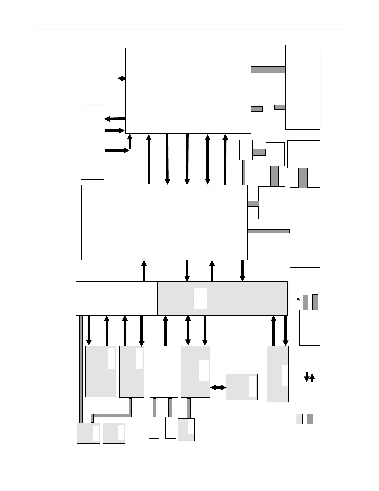
Main Board/NIBP
The main board houses the central processor and is the
focal point for all data in the 250. The board is responsible
for the following:
•
Receives processed FECG, Ultrasound, UA, and
MECG data from the DSP board.
•
Formats DSP data for display.
•
Passes display data to the DSP board display
FPGA which in turns drives the LCD panel.
•
Writes the processed data to the recorder board.
•
Receives front panel keypad/trimknob data from
the UI board.
•
Communicates parameter data to the rear panel
communications ports.
•
Passes parameter telemetry data to the DSP board
for processing.
•
Inputs keypad data from rear panel comm. Board
and sends it to the recorder board.
•
Executes diagnostics
o
Reports its own main failures
o
Reports UI keypad and DSP failures
o
Recorder test pattern and display test
pattern
o
Audio test pattern
•
Provides NIBP processing subsystem &
communicat es to the external Pneumatics
PWA.
DSP/Display Interface Board
The DSP/Display interface board forms the
ridge between the frontend parameters and
the main board central processor. It also has
the function of display interface. It interfaces
the Main board to the LCD panel by
roviding a dual port memory to the main
oard and a graphics engine driving the LCD
anel. The board is responsible for the
following:
•
Interfaces to front-end motherboard
which holds the parameter boards.
•
DSP Processing of FECG, MECG,
UA, and Dual Ultrasound data thus
converting analog data to heart rates
and pressure values.
•
Sending of processed data to main
board.
•
Pass through of MSpO2 OEM
module serial communication lines to
the main board (no processing done
by DSP).
•
Provides status of patient cables
plugged in to monitor to the main
board.
•
Drives the LCD display panel by
generating the video graphics through
the FPGA chip and sending data to
the decoder board which then
connects to the LCD display.
•
Interfaces the video to the main board
processor through a dual port memory
•
Pass through of front panel serial
comm lines to the main board
.
Digitally Processed
Analog Parameter
Data
Un-Processed Analog
Parameter Data
From telemetr
Graphics Data
for display
Pass through
MSpO2 serial data
& Reset
Recorder Board
Interfaces main board serial data to recorder
rinthead
Provides regulated power to printhead
Provides sensor data from recorder door, paper
out & paper misload to main board
Pass through UI
Keypad serial data
Front-end
Motherboard
Connects front-
end bds together
distributing
isolated power
and un-isolated
ower.
Passes through
all analog signals
to the DSP board
for processing.
FECG/UA Board
Converts fetal ECG to analog
signal for processing
Converts pressure signal to
analog for DSP signal
rocessing
MECG Board
Converts 3 lead maternal ECG
signals to analog signal for
DSP processing
Dual Ultrasound Board
Provides doppler shift analog
signals to DSP board
SpO2 Carrier Board
Carries MSpO2 modules
connecting to FE mthbd
MSpO2
Module
Provides serial
MSpO2 data to
main board
Isolated Power Supply
Provides isolated power to all
front-end boards excluding US
oard
All
Analog
Signals
Telemetry
US data
UI Keypad
Passes all button closures and trimknob data to
main bd via DSP board.
Provides the chart light & key backlight function
under main board control.
Interfaces serially to the main bd.
Serial keypad
data cable
Comm Board
Interfaces ext keypad to main board
Interfaces ext telemetry analog signals to main bd
Interfaces legacy Spectra analog central station b
sendin
.
Telemetry
analo
si
nals
Keypad
signals
Analog HR
outputs
Analog HR signal
with Mode Info
Analog HR signal
with Mode Info
Lead selection,
Pacer enable, test
si
nal enable
Serial digital
MpO2 data
MSpO2 Resets
Serial digital
MSpO2 data
FECG +
MECG
Front panel
Connector
FECG UA cables (2)
MECG
cable
Analog HR signal
with Mode Info
FECG & UA signals
Power for MspO2,
FECG, and MECG
boards
System +20 volts
for switching
Serial digital
MSpO2 data
MSpO2
Resets
UI Volume
Keypad
Holds volume
& alarm
cancel buttons
US1
Connector
US2
Connector
MSpO2 FP
Connector
Bd
UA Front
Panel
Connector
US1 cable
US2 cable
MS
O2 cable
MSpO2 sensor data
Isolated
Isolated
Denotes Patient
Isolated Sections
Video Decoder
Board
Translates 12
it color to 1 bit
color (2 colors)
LCD
Panel
320 X 240
Inverter
Module
Volume
data cable
Video Flex
data cable
DSP/Decoder
Video cable
DSP Inverter
Power cable
LCD Inverter
cable
(part of LCD)
Recorder Serial
data/status
Cable
System Power
Supply
+5, +12, +15, -15
To Main
Board
To Recorder
Board
Power Cables
Power Cable from
system power
supply
Power Cable from
system power
supply
Pneumatics
Board
Contains pump,
Denotes
Plug-in
connections
Isolated
Isolated
Isolated
Isolated
Partially
Isolated
Denotes cables
Isolated

 Loading...


