Appendix H: Remote Alarm Connector
267
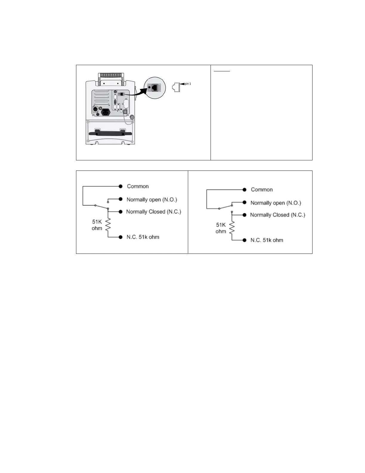
The following table shows the Remote Alarm connector wiring diagram:
Pinout:
1) Common
2) N.O
3) Do not use
4) Do not use
5) Do not use
6) Do not use
7) N.C.
8) N.C. 51K
Normal Mode:
Alarm Mode:
The remote alarm connector provides access to a relay that is normally activated,
but deactivates when an alarm status occurs, or the main power is turned off.
In Normal mode, the “N.O.” contact to common is disconnected, while the “N.C.”
contact to common is connected. The “N.C. 51K” is connected to common
through a 51K ohm resistor required by some alarm systems.
In Alarm mode, the “N.O.” contact to common is connected, while the “N.C.” and
“N.C. 51K” contacts to common are disconnected.

 Loading...