EasyManuals Logo

GE iVent 201 Series User Manual

GE iVent 201 Series
290 pages
To Next Page IconTo Next Page
To Previous Page IconTo Previous Page
Page #45 background imageLoading...
Page #45 background image
2 Setting up
33
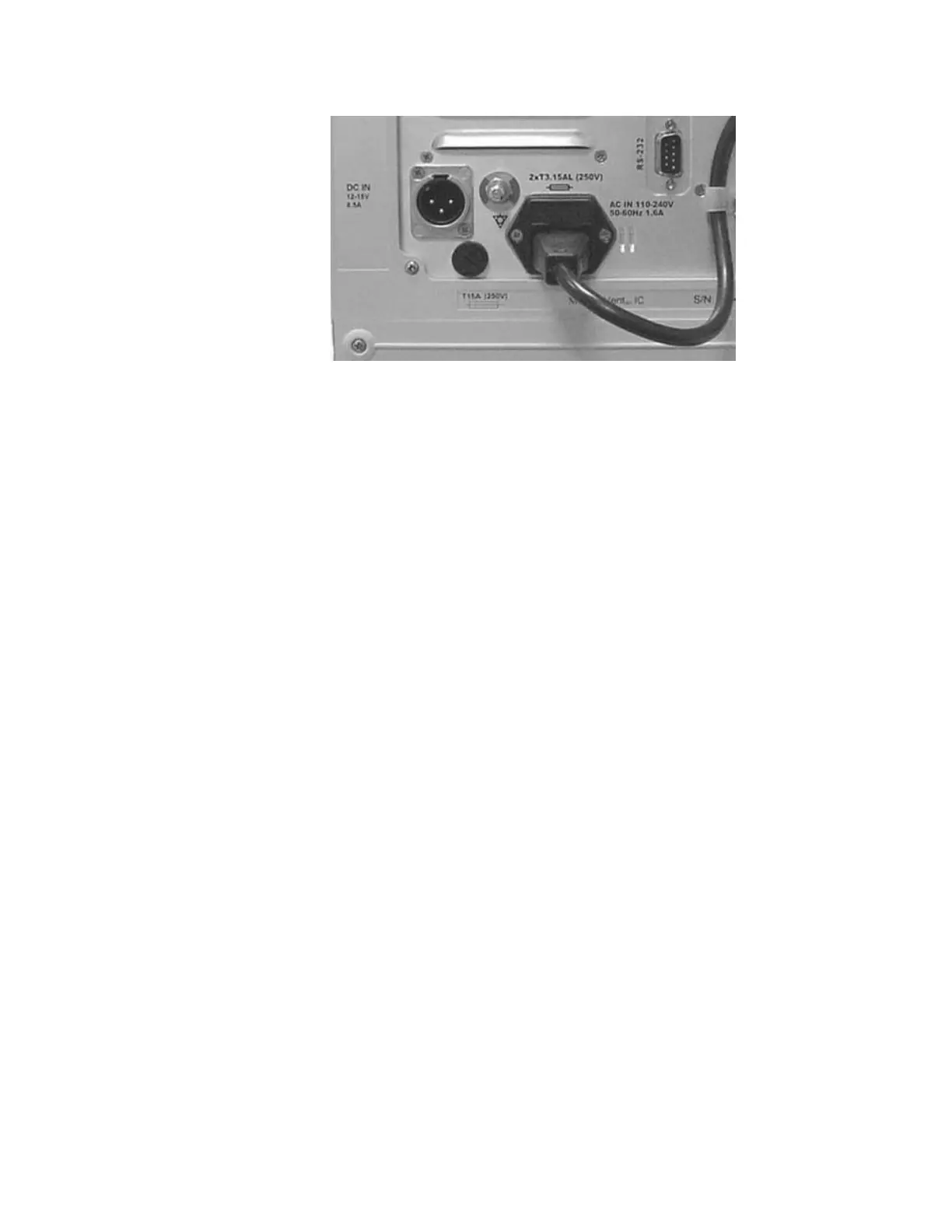
Figure 5: External AC and DC power supply sockets. The AC power cord is connected to
the power inlet and fastened with the clip.
NOTE To prevent accidental disconnection of the AC power cord, secure it
with the cable clip
WARNING If the power cord is damaged, worn, or frayed, replace it
immediately
NOTE Before you turn off the iVent
TM
201 change the mode to Standby
mode (Page 61)
When the ventilator is in operation, icons at the bottom section of the screen
indicate the power state (Figure 6).

Table of Contents

Questions and Answers:

Question and Answer IconNeed help?

Do you have a question about the GE iVent 201 Series and is the answer not in the manual?

GE iVent 201 Series Specifications

General IconGeneral
BrandGE
ModeliVent 201 Series
CategoryMedical Equipment
LanguageEnglish

Related product manuals