2 Setting up
45
3. Connect the one-way valve to one end of a 1-2’ length of 22mm corrugated
tubing.
4. Connect the other end of the tubing to the ventilator outlet. Fasten the one-
way valve to the humidifier inlet. Be sure the directional arrow on the valve is
pointing towards the patient end of the circuit.
5. Connect the Male and Female clear sensor tubing connectors to the Male
and Female luer inlets on the front of the iVent201 as described above in
Patient Circuit, page 40.
6. Connect the blue Expiratory Sensor tube to the luer connector marked with a
blue dot on the front of the ventilator.
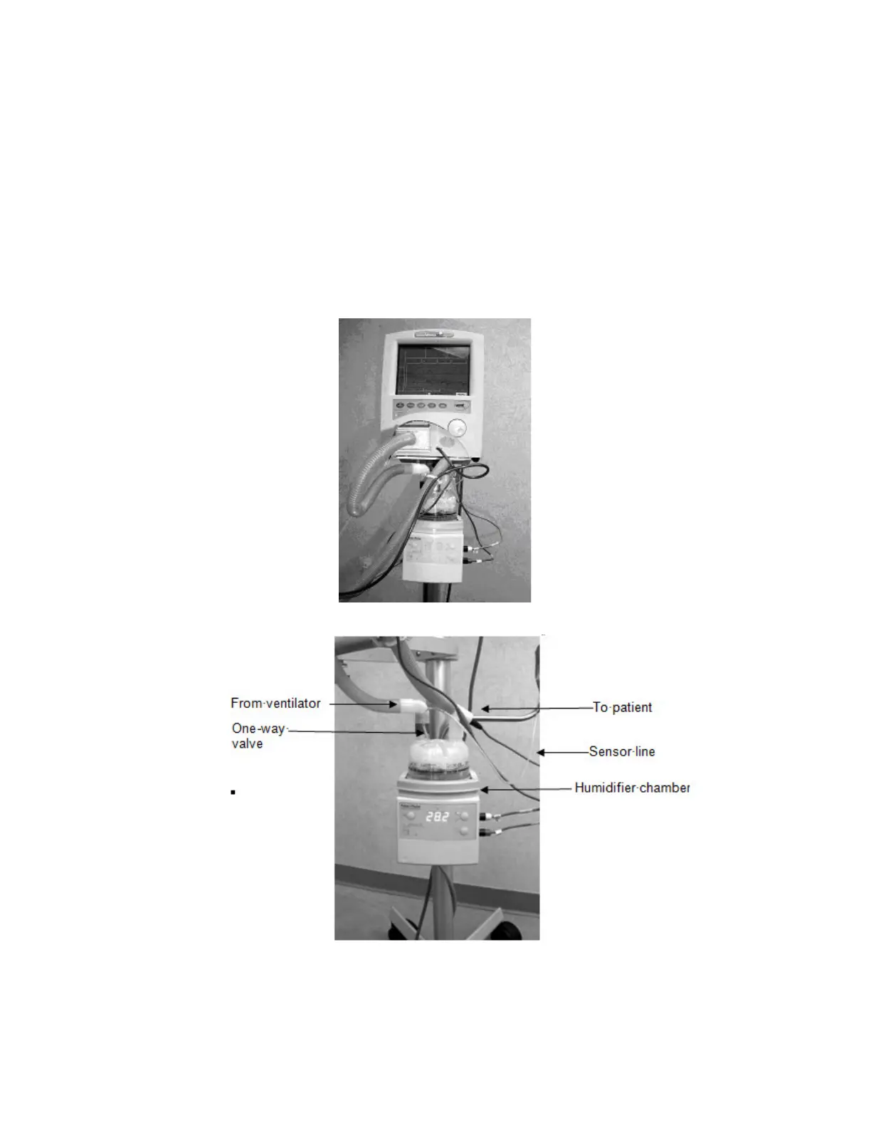
Figure 15: The iVent
TM
201 shown connected to a Fisher and Paykel Heated Humidifier Model MR850
Figure 16: Heated Humidifier Connections
NOTE If not using a heated wire circuit, placement of a water trap at the
 Loading...