Chapter 2. CPU Features & Specifications
GFK-2222AD April 2018 89
2.3.1 CPE030/CRE030 and CPE040/CRE040
Serial Ports CPE030/CRE030 & CPE040/CRE040
Each CPU has three independent, on-board serial ports, accessed by connectors on
the front of the module. COM1 and COM2 provide serial interfaces to external
devices; either can be used for firmware upgrades. The third serial port is a dedicated
Ethernet Station Manager port. For serial port pin assignments, electrical isolation
and details on serial communications, refer to Chapter 5.
Ethernet Ports CPE030/CRE030 & CPE040/CRE040
Two RJ45 ports support Ethernet communications. Refer to RX7i Embedded
Ethernet Interface for details.
Indicators CPE030/CRE030 & CPE040/CRE040
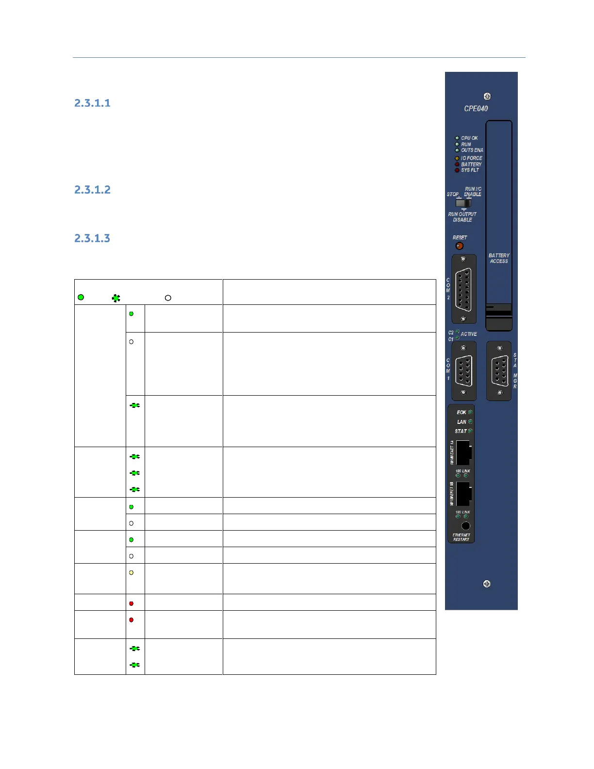
Seven CPU LEDs indicate the operating status of various CPU functions.
Two Comm LEDs indicate activity on COM1 and COM2.
CPU has passed its power-up diagnostics and is
functioning properly.
CPU problem. RUN and OUTPUTS ENABLED LEDs
may be blinking in an error code pattern, which can
be used by technical support for diagnostics. This
condition and any error codes should be reported to
your technical support representative.
Blinking Green
Other LEDs off
CPU in Stop/Halt state; possible watchdog timer
fault. Refer to the fault tables. If PME cannot
connect, cycle power with battery attached and
refer to fault tables.
CPU is in boot mode and is waiting for a firmware
update through a serial port.
Override is active on a bit reference
(Not used by CRE030 or CRE040.)
Battery has failed or is not attached.
CPU is in Stop/Faulted mode because a fatal fault
has occurred.
Signals activity on corresponding serial port.
Figure 29:
CPE040 Front
View

 Loading...