Chapter 6. Serial I/O, SNP & RTU Protocols
230 PACSystems* RX7i, RX3i and RSTi-EP CPU Reference Manual GFK-2222AD
Information Fields
All message fields, other than the Station Address field, Function Code field, and Error Check field are
called, generically, information fields. Information fields contain additional information required to
specify or respond to a requested function. Different types of messages have different types or numbers
of information fields. (Details on information fields for each message type and function code are found in
RTU Message Descriptions. Some messages (Message 07 Query and Message 17 Query) do not have
information fields.
Examples
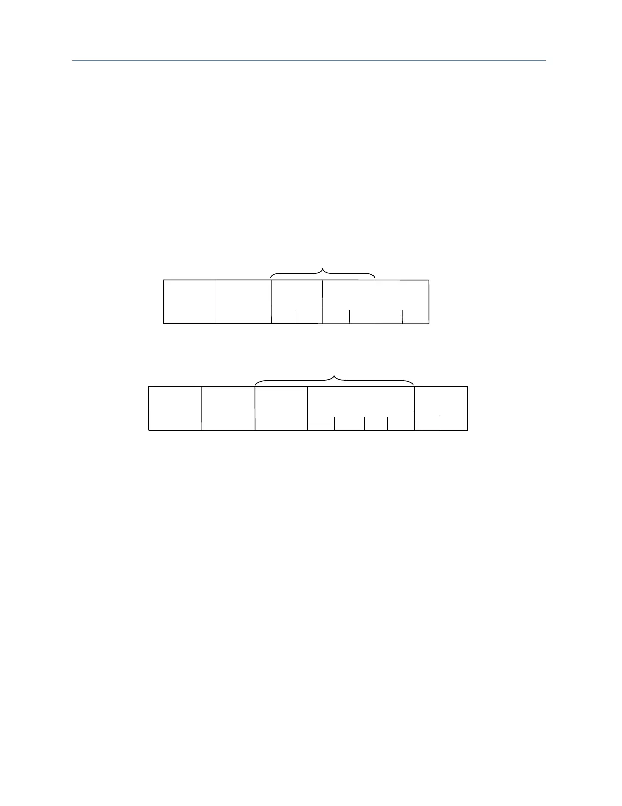
As shown in the following figure, the information fields for message READ OUTPUT TABLE (01) Query
consist of the Starting Point No. field and Number of Points field. The information fields for message
READ OUTPUT TABLE (01) Response consist of the Byte Count field and Data field.
Figure 50: RTU Read Output Table Example
Some information fields include entries for the range of data to be accessed in the RTU slave.
Note: Data addresses are 0-based. This means you will need to subtract 1 from the actual address
when specifying it in the RTU message. For message (01) READ OUTPUT TABLE Query, used
in the example above, you would specify a starting data address in the Starting Point No.
field. To specify %Q0001 as the starting address, you would place the address %Q0000 in
this field. Also, the value placed in the Number of Points field determines how many %Q bits
are read, starting with address %Q0001. For example:
▪ Starting Point No. field = %Q0007, so the starting address is %Q0008.
▪ Number of Points field = 16 (0010h), so addresses %Q0008 through %Q0023 will be read.
Error Check Field
The Error Check field is two bytes in length and contains a cyclic redundancy check (CRC-16) code. Its
value is a function of the contents of the station Address, Function code, and Information field. The
details of generating the CRC-16 code are described in Cyclic Redundancy Check (CRC). Note that the
Information field is variable in length. To properly generate the CRC-16 code, the length of frame must
be determined. To calculate the length of a frame for each of the defined function codes, see Calculating
the Length of Frame.

 Loading...