Chapter 2. CPU Features & Specifications
104 PACSystems* RX7i, RX3i and RSTi-EP CPU Reference Manual GFK-2222AD
LED Indicators (LEDs)
Ethernet Status Indicators
There are two LEDs (Yellow/Green) for each Ethernet ports of LAN1 and LAN2, which are embedded in
the RJ45 connectors. The green LED indicates an Ethernet connection has been established. The yellow
LED indicates packet traffic.
Module Status Indicators
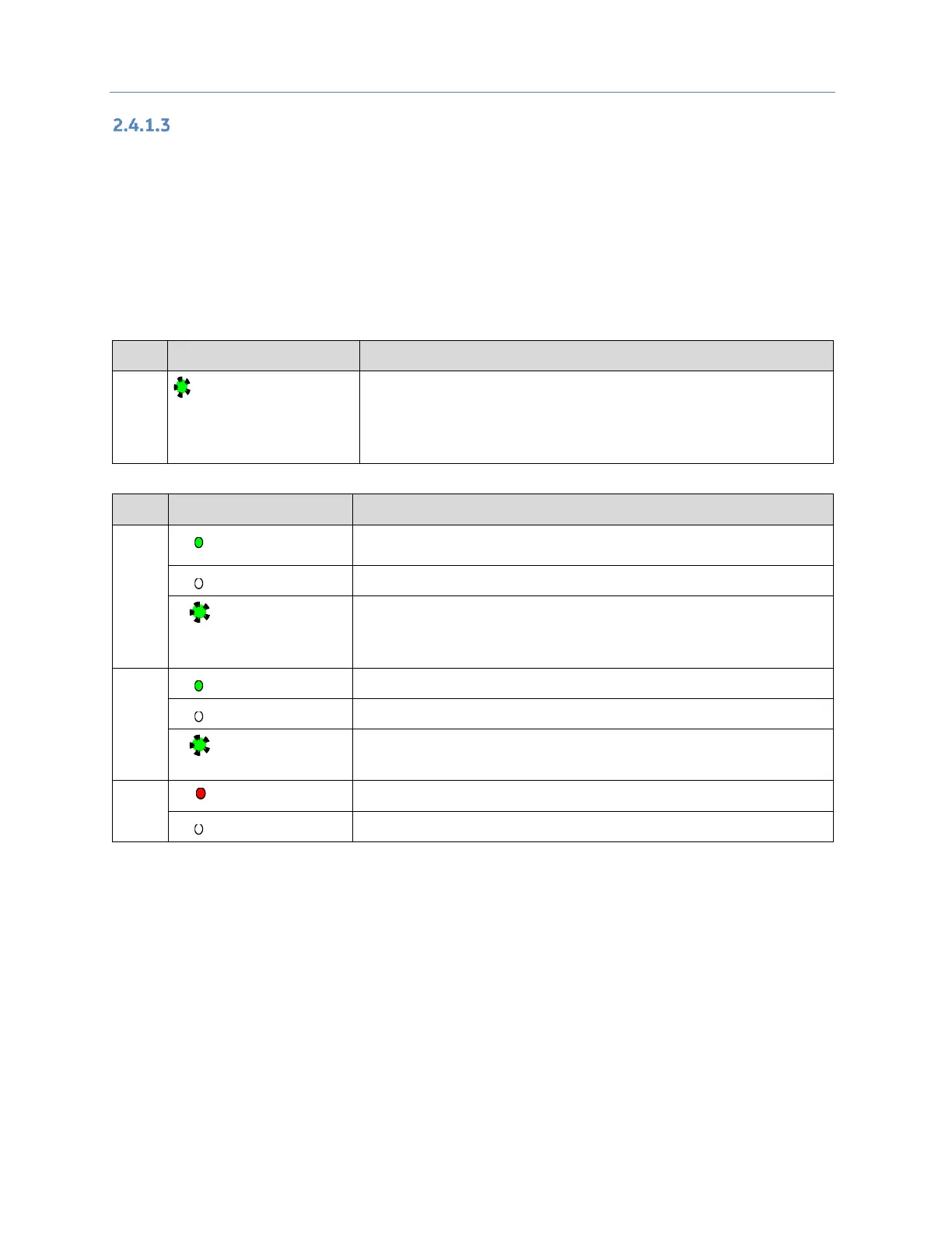
There are three LEDs and one membrane pushbutton on the front panel, as shown in Figure 32. The table
below describes the behavior of each LED:
Operating State (at Power-Up)
Blinking; All other
LEDs off
This LED indicates the status of PLC during powering up. It starts
blinking 6 seconds after applying power to the PLC and remains in
this state for up to 15 seconds. After this all LEDs turn off and will
remain in this state until PLC is ready.
Operating State (after Power-Up)
PLC has passed its power-up diagnostics and is functioning
properly
Power is not applied or PLC has a problem.
Blinking; All
other LEDs off
PLC in STOP/Halt state; possible watchdog timer fault. If the
programmer cannot connect, cycle power and refer to the fault
tables.
Blinking; All
other LEDs off
Indicates that PLC has encountered a fatal error and is blinking the
error code.
PLC is in STOP/Faulted mode: a fatal fault has occurred.
No fatal faults detected.

 Loading...