7-42 PQM Power Quality Meter GE Power Management
7.3 MODBUS MEMORY MAP 7 MODBUS COMMUNICATIONS
7
CLEAR DATA
continued
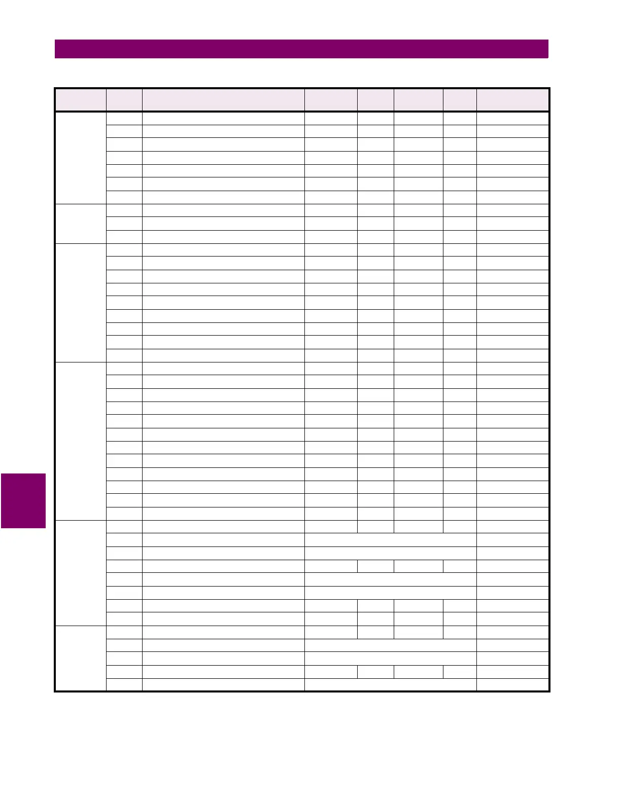
103D Clear Max THD Values 0 to 1 1 --- F31 0 = NO
103E Clear Pulse Input Values 0 to 1 1 --- F31 0 = NO
103F Clear Event Record 0 to 1 1 --- F31 0 = NO
1040 Clear All Demand Values 0 to 1 1 --- F31 0 = NO
1041 Clear Frequency Values 0 to 1 1 --- F31 0 = NO
1042 Reserved
1043 Reserved
DNP 1044 DNP Port 0 to 3 1 --- F47 0 = NONE
1045 DNP Slave Address 0 to 255 1 --- F1 0
1046 DNP Turnaround Time 0 to 100 10 ms F1 10 ms
TARIFF 1047 Tariff Period 1 Start Time 0 to 1439 1 minutes F1 0 min.
1048 Tariff Period 1 Cost per MWh 1 to 50000 1 ¢
×
0.01 F1 10.00 ¢
1049 Tariff Period 2 Start Time 0 to 1439 1 minutes F1 0 min.
104A Tariff Period 2 Cost per MWh 1 to 50000 1 ¢
×
0.01 F1 10.00 ¢
104B Tariff Period 3 Start Time 0 to 1439 1 minutes F1 0 min.
104C Tariff Period 3 Cost per MWh 1 to 50000 1 ¢
×
0.01 F1 10.00 ¢
104D Reserved
104E Reserved
104F Reserved
CURRENT
/VOLTAGE
CONFIG.
1050 Phase CT Primary 0 to 12000
****
5 A F1 100 A
1051 Neutral Current Sensing 0 to 2 1 --- F16 0 = OFF
1052 Neutral CT Primary 5 to 6000 5 A F1 100 A
1053 VT Wiring 0 to 6 1 --- F15 0 = OFF
1054 VT Ratio 10 to 35000 1 0.1 xratio F1 1.0:1
1055 VT Nominal Secondary Voltage 40 to 600 1 V F1 120 V
1056 Nominal Direct Input Voltage 40 to 600 1 V F1 600 V
1057 Nominal Frequency 50 to 60 10 Hz F1 60 Hz
1058 CT Wiring 0 to 3 1 --- F44 0=A,B AND C
1059 Reserved
to
↓
↓
↓
↓
↓
↓
105F Reserved
ANALOG
OUTPUT 1
1060 Analog Output 1 Main Type 0 to 59 1 --- F14 0=NOT USED
1061 Analog Output 1 Main Min Value See Analog Output Range Table on page 7–63 0
1062 Analog Output 1 Main Max Value See Analog Output Range Table on page 7–63 0
1063 Analog Output 1 Alternate Type 0 to 59 1 --- F14 0=NOT USED
1064 Analog Output 1 Alternate Min Value See Analog Output Range Table on page 7–63 0
1065 Analog Output 1 Alternate Max Value See Analog Output Range Table on page 7–63 0
1066 Reserved
1067 Analog Output 1 Serial Value 1 --- F2 0
ANALOG
OUTPUT 2
1068 Analog Output 2 Main Type 0 to 59 1 --- F14 0=NOT USED
1069 Analog Output 2 Main Min Value See Analog Output Range Table on page 7–63 0
106A Analog Output 2 Main Max Value See Analog Output Range Table on page 7–63 0
106B Analog Output 2 Alternate Type 0 to 59 1 --- F14 0=NOT USED
106C Analog Output 2 Alternate Min Value See Analog Output Range Table on page 7–63 0
Table 7–10: PQM MEMORY MAP (Sheet 28 of 40)
GROUP ADDR
(HEX)
DESCRIPTION RANGE STEP
VALUE
UNITS and
SCALE
FORMAT FACTORY DEFAULT
Notes: * Data type depends on the Command Operation Code. ** Any valid Actual Values or Setpoints address.
*** Maximum Setpoint value represents “OFF”. **** Minimum Setpoint value represents “OFF”.
***** Maximum Setpoint value represents “UNLIMITED”.
 Loading...


