GE Power Management PQM Power Quality Meter 4-23
4 PROGRAMMING 4.3 S2 SYSTEM SETUP
4
Each of the analog outputs can be assigned to two of the parameters listed in Table 4–3: ANALOG OUT-
PUT PARAMETERS. The analog output main selection is the default selection and a programmable switch
input can be programmed to multiplex the
ANALOG OUTPUT ALT
selection to the same output depending
upon the open or closed state of the switch input. See Section 4.3.4: SWITCH INPUTS on page 4–27 for
details about configuring a switch input. If no switch input is assigned as an analog output multiplexer, the
analog output main selection will be the only parameter which appears at the analog output terminals. The
ability to multiplex two different analog output quantities on one analog output effectively gives the PQM
eight analog outputs. The table below shows the criteria used by the PQM to decide whether the output is
based on MAIN or ALT settings.
•
MAIN/ALT 4 mA VALUE:
This message appears for each analog output and allows the user to assign a
numeric value which corresponds to the 4 mA end of the 4 to 20 mA signal range (T20 option) or the 0 mA
end of the 0 to 1 mA signal range (T1 option). The numeric value range will depend upon which parameter
is selected. See Table 4–3: ANALOG OUTPUT PARAMETERS below for details. Note that if the T20
option is installed and the
ANALOG OUTPUT RANGE
setpoint is set to
0-20 mA
, this message represents the 0
mA end of the signal range.
•
MAIN/ALT 20 mA Value:
This message appears for each analog output and allows the user to assign a
numeric value which corresponds to the 20 mA end of the 4 to 20 mA signal range (T20 option) or the 1
mA end of the 0 to 1 mA signal range (T1 option). The numeric value range will depend upon which param-
eter is selected. See Table 4–3: ANALOG OUTPUT PARAMETERS
below for details.
If the 4 mA (or 0 mA) value is programmed to be higher than the 20 mA (or 1 mA) value, the analog output
will decrease towards 4 mA (or 0 mA) as the value increases and the analog output will increase towards
20 mA (or 1 mA) as the value decreases. If the 4 mA (or 0 mA) and 20 mA (or 1 mA) values are pro-
grammed to an identical value, the output will always be 4 mA (or 0 mA).
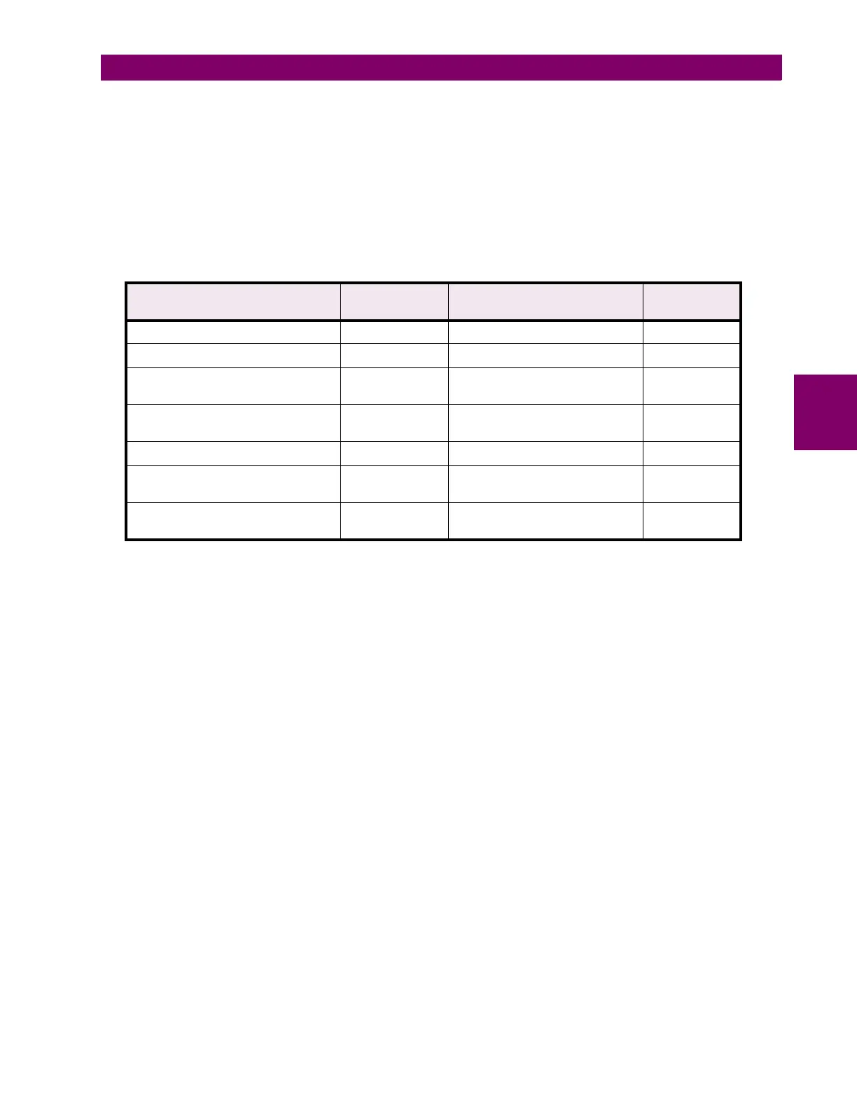
Table 4–2: ANALOG OUTPUT SELECTION CRITERIA
CONDITION PRESENT ‘MAIN’
PARAMETER
‘ALT’ PARAMETER OUTPUT
BASED ON
Any condition
NOT USED NOT USED
MAIN
Control option ‘C’ not installed any not available MAIN
Switch assigned to
SELECT
ANALOG OUTPUT
and is disabled
any NOT USED MAIN
Switch assigned to
SELECT
ANALOG OUTPUT
and is enabled
any NOT USED MAIN
Any condition
NOT USED
anything other than
NOT USED
ALT
Switch assigned to
SELECT
ANALOG OUTPUT
and is disabled
NOT USED
anything other than
NOT USED
ALT
Switch assigned to
SELECT
ANALOG OUTPUT
and is enabled
any anything other than
NOT USED
ALT

 Loading...


