4-24 PQM Power Quality Meter GE Power Management
4.3 S2 SYSTEM SETUP 4 PROGRAMMING
4
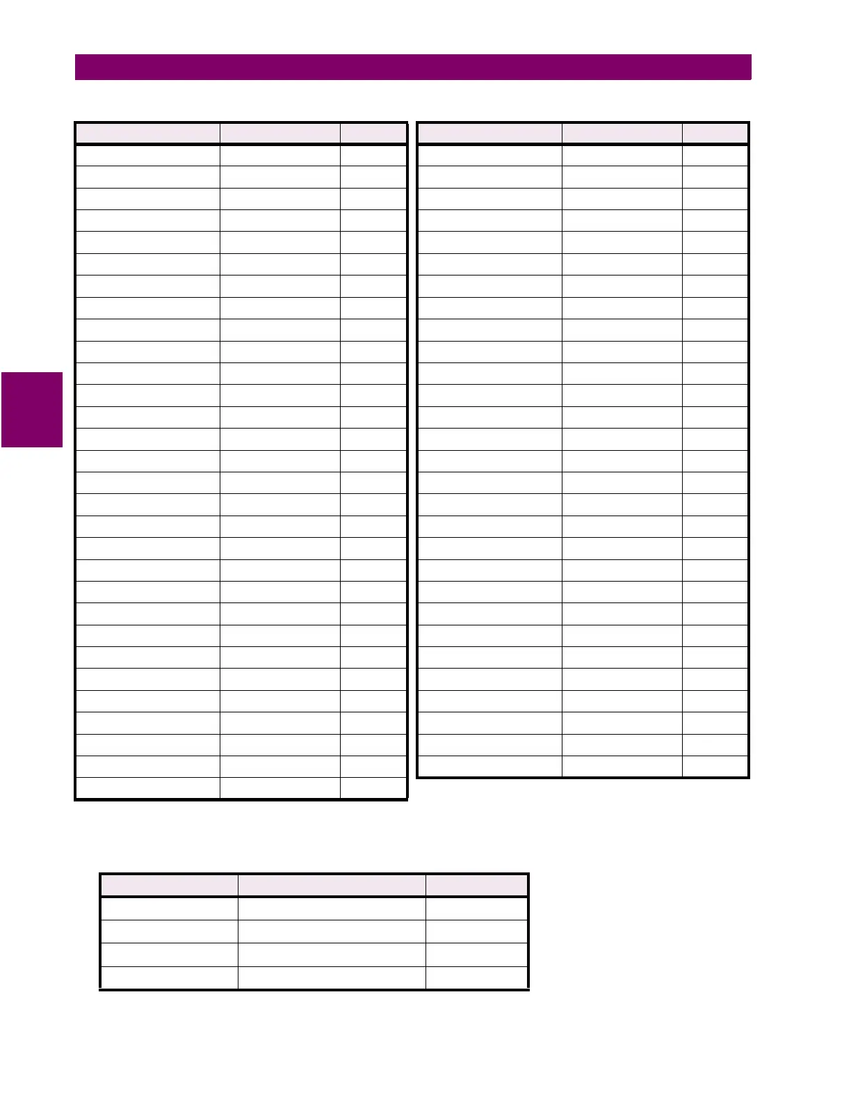
Table 4–3: ANALOG OUTPUT PARAMETERS
•
ANALOG OUTPUT PARAMETER – Serial Control
: When the Analog Output parameter is set to Serial
Control, the analog output(s) reflect a value in proportion to the serial value written to a specific register
within the PQM memory map. The locations are as described in the table below.
PARAMETER RANGE STEP PARAMETER RANGE STEP
Phase A Current 0 to 150% 1% Phase B kVA 0 to 65400 1 kVA
Phase B Current 0 to 150% 1% Phase C PF 0.01 lead to 0.01 lag 0.01
Phase C Current 0 to 150% 1% Phase C kW –32500 to +32500 1 kW
Neutral Current 0 to 150% 1% Phase C kvar –32500 to +32500 1 kvar
Average Phase Current 0 to 150% 1% Phase C kVA 0 to 65400 1 kVA
Current Unbalance 0 to 100.0% 0.1% 3 Phase +kWh Used 0 to 65400 1 kWh
Voltage Van 0 to 200% 1% 3 Phase +kvarh Used 0 to 65400 1 kvarh
Voltage Vbn 0 to 200% 1% 3 Phase –kWh Used 0 to 65400 1 kWh
Voltage Vcn 0 to 200% 1% 3 Phase –kvarh Used 0 to 65400 1 kvarh
Voltage Vab 0 to 200% 1% 3 Phase kVAh Used 0 to 65400 1 kVAh
Voltage Vbc 0 to 200% 1% Ph. A Current Demand 0 to 7500 1 A
Voltage Vca 0 to 200% 1% Ph. B Current Demand 0 to 7500 1 A
Average Phase Voltage 0 to 200% 1% Ph. C Current Demand 0 to 7500 1 A
Average Line Voltage 0 to 200% 1% Neutral Current Demand 0 to 7500 1 A
Voltage Unbalance 0 to 100.0% 0.1% 3 Phase kW Demand –32500 to +32500 1 kW
Frequency 00.00 to 75.00 Hz 0.01 Hz 3 Phase kvar Demand –32500 to +32500 1 kvar
3 Phase PF 0.01 lead to 0.01 lag 0.01 3 Phase kVA Demand 0 to 65400 1 kVA
3 Phase kW –32500 to +32500 1 kW 3 Phase Current THD 0.0 to 100% 0.1%
3 Phase kvar –32500 to +32500 1 kW 3 Phase Voltage THD 0.0 to 100% 0.1%
3 Phase kVA 0 to 65400 1 kVA Phase A Current THD 0.0 to 100% 0.1%
3 Phase MW –3250.0 to +3250.0 0.1 MW Phase B Current THD 0.0 to 100% 0.1%
3 Phase Mvar –3250.0 to +3250.0 0.1 Mvar Phase C Current THD 0.0 to 100% 0.1%
3 Phase MVA 0 to 6540.0 0.1 MVA Voltage Van THD 0.0 to 100% 0.1%
Phase A PF 0.01 lead to 0.01 lag 0.01 Voltage Vbn THD 0.0 to 100% 0.1%
Phase A kW –32500 to +32500 1 kW Voltage Vcn THD 0.0 to 100% 0.1%
Phase A kvar –32500 to +32500 1 kvar Voltage Vab THD 0.0 to 100% 0.1%
Phase A kVA 0 to 65400 1 kVA Voltage Vbc THD 0.0 to 100% 0.1%
Phase B PF 0.01 lead to 0.01 lag 0.01 Neutral Current THD 0.0 to 100% 0.1%
Phase B kW –32500 to +32500 1 kW Serial Control –32500 to +32500 1 Unit
Phase B kvar –32500 to +32500 1 kvar
ANALOG OUTPUT MODBUS REGISTER REGISTER
Analog Output 1 Analog Output1 Serial Value 1067
Analog Output 2 Analog Output2 Serial Value 106F
Analog Output 3 Analog Output3 Serial Value 1077
Analog Output 4 Analog Output4 Serial Value 106F

 Loading...


