124 ADV200 • Quick start up guide
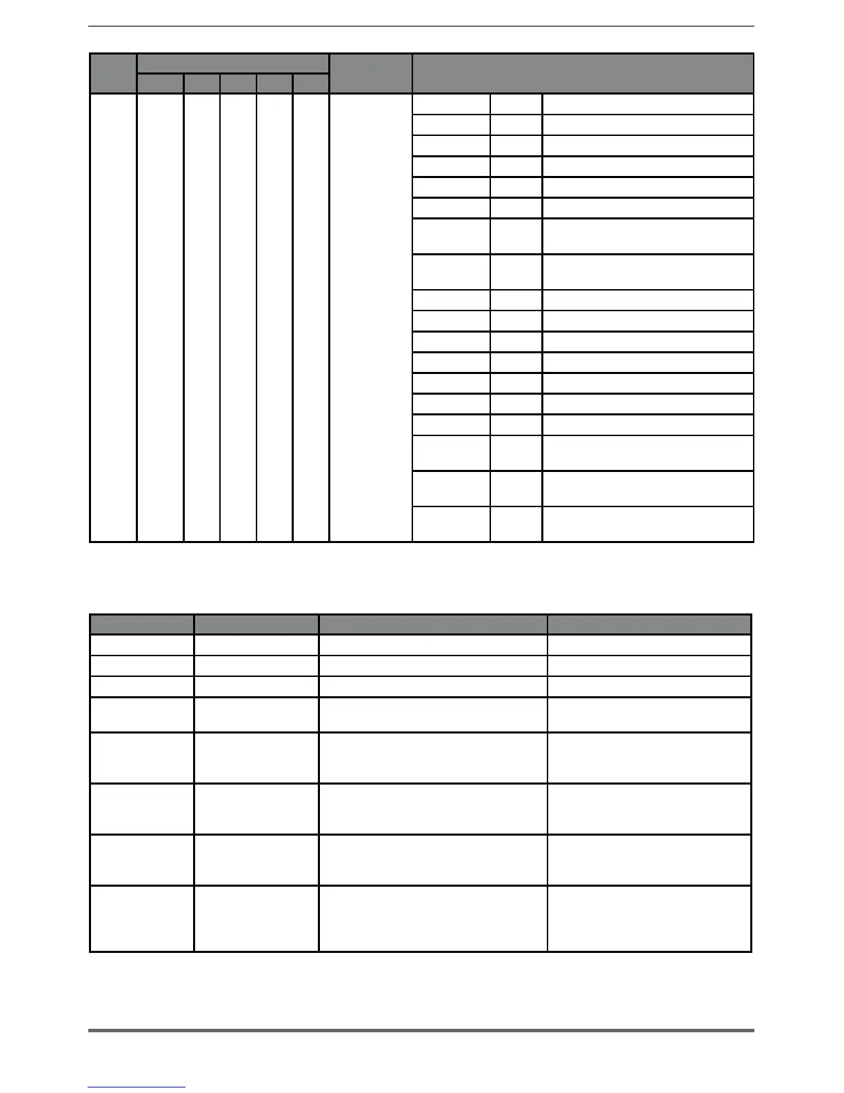
Bit
Value
Name
Description
D7..D4 D3 D2 D1 D0
0AH Checksum of transmitted data is wrong
0BH Incorrect command code
0CH Wrong number of transmitted data
0DH Illegal transmitted command argument
0FH Wrong access authorization specified
0EH Selected field has READ ONLY status
10H Data field (re) definition not executable
due to field size
11H Specified address is not available in
selected field
12H Selected field does not yet exist
00H No encoder error, no error message
03H Data field operations disabled
04H Analog monitoring inoperative
08H Counting register overflow
01H Encoder analog signals are unreliable
02H Wrong synchronisation or offset
05H-
07H
Encoder-internal hardware fault, no
operation possible
1CH-
1DH
Error in sampling, no operation possible
1EH Permissible operation temperature is
exceeded
● Speed fbk loss [22] alarm with Resolver
Code Name Error description Possible solution
0x00000001 D0 FAULT REGISTER Configuration parity error Reset Resolver card
0x00000002 D1 FAULT REGISTER Phase error exceeds phase lock range
0x00000004 D2 FAULT REGISTER Velocity exceeds maximum tracking rate
0x00000008 D3 FAULT REGISTER
Tracking error exceeds LOT (Loss of Signal)
threshold
0x00000010 D4 FAULT REGISTER
SIN/COS inputs exceed DOS (Degradation of
signal) mismatch threshold
Check the connection of the Resolver
input pins (SIN-,SIN+,COS-,COS+),
check PAR 2128
0x00000020 D5 FAULT REGISTER
SIN/COS inputs exceed DOS (Degradation of
signal) over range threshold
Check the connection of the Resolver
input pins (SIN-,SIN+,COS-,COS+),
check PAR 2126
0x00000040 D6 FAULT REGISTER
SIN/COS inputs below LOS (Loss of Signal)
threshold
Check the connection of the Resolver
input pins (SIN-,SIN+,COS-,COS+),
check PAR 2124
0x00000080 D7 FAULT REGISTER SIN/COS inputs clipped
Check if any of the Resolver input pins
(SIN-,SIN+,COS-,COS+) are shorted
with power input or ground of the
resolver board

 Loading...


