Maintenance Manual April 2018
Programmed Maintenance Procedures
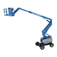
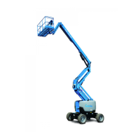
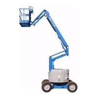
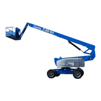
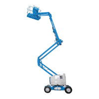
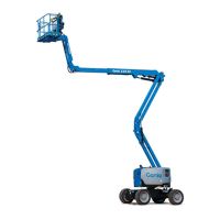
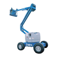
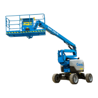
150 S
®
Booms • Z
®
Booms Part No. 1268489GT
9 Lift the wheels or tracks off the ground and
then place jack stands under the drive chassis
for support.
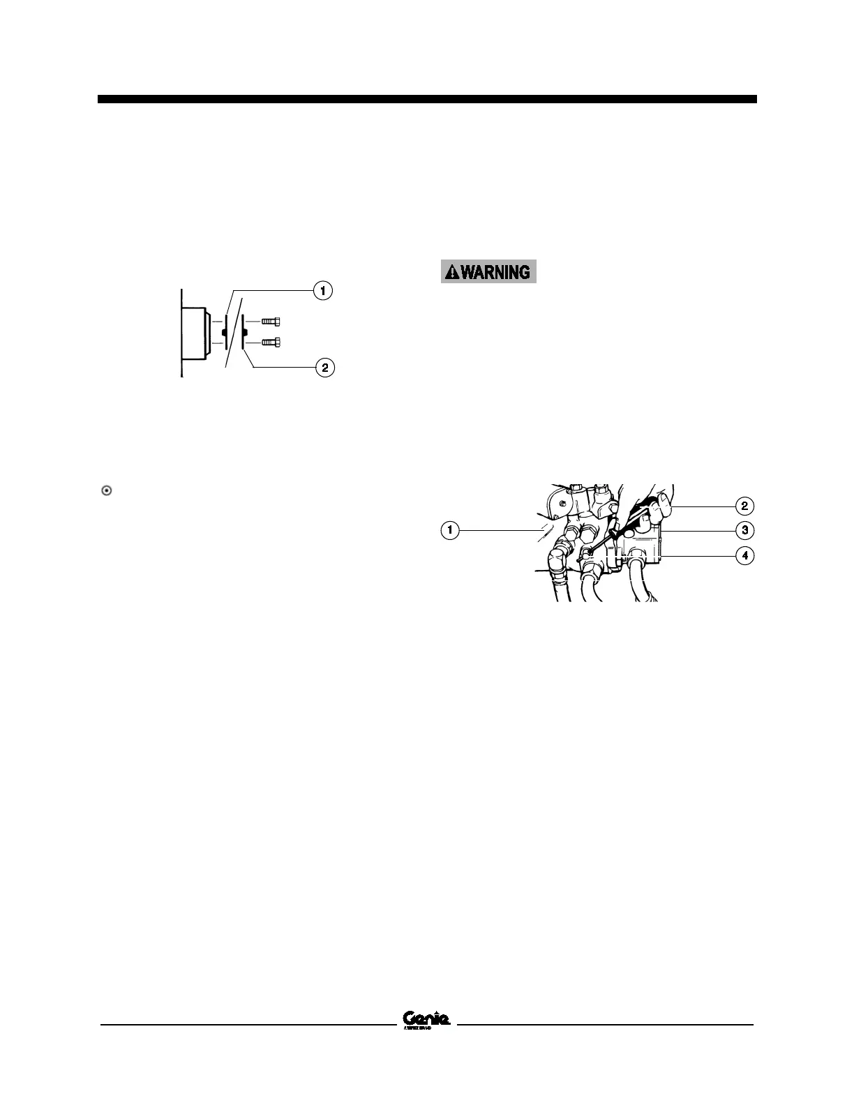
10 Disengage the drive hubs by turning over the
drive hub disconnect caps on each steer /
square-end wheel hub.
1 brake disengaged position
2 brake engaged position
11 Manually rotate each steer / square-end wheel
or track.
Result: Each steer / square-end wheel or track
should rotate with minimum effort.
Note: TRAX Models: Due to the additional
components of the track system, which increase
rotational friction, the track may not be able to be
rotated manually.
12 Re-engage the drive hubs by turning over the
hub disconnect caps. Rotate each wheel or
track to check for engagement. Raise the
machine, remove the jack stands and lower
the machine.
Collision hazard. Failure to
re
-engage the drive hubs could
result in death or serious injury
and property damage.
Models with Hydraulic Pump free-wheel valve:
13 Be sure the free-wheel valve on the drive
pump is closed (clockwise).
Note: The free-wheel valve should always remain
closed.
1 drive pump
2 screwdriver
3 lift pump
4 free-wheel valve
Note: The location of the free-wheel valve may vary
by model.
 Loading...