12
796688 (4188-657)_ I1.2 / 02.02
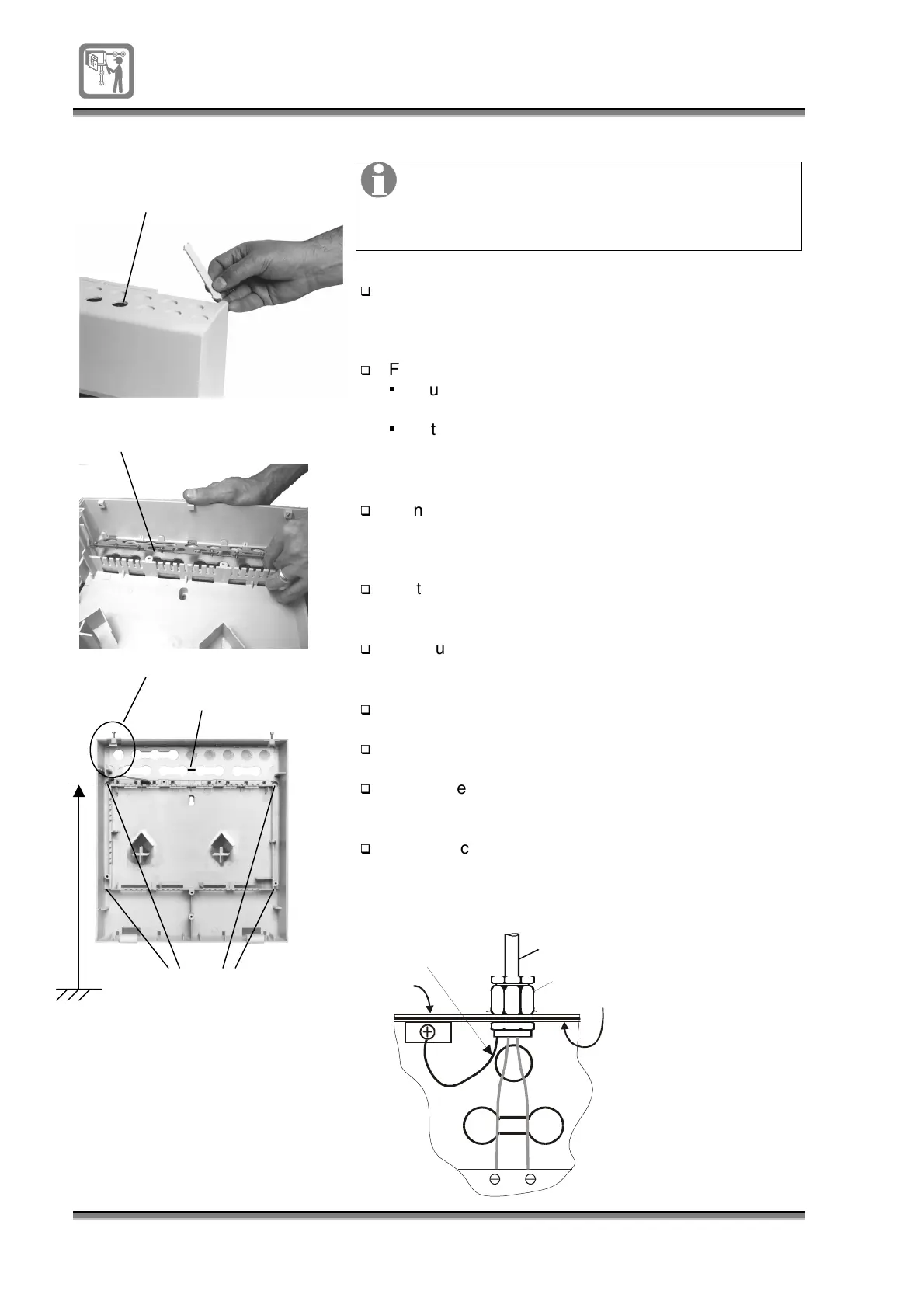
To mount the backbox
on wall
Cable entry points
Gland plate
Mains cable entry points
Cable tie
Fixing points
Floor level
Panel dimensions:
Height 375mm
Width 355mm
Depth 115mm
Ensure there is at least 100mm clearance
around each side of the panel. Also there must
be sufficient space beneath the panel assembly
to allow the door to hang open.
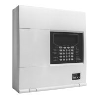
Knockout the required cable entry points from the
backbox or where appropriate snap off the required
cable entry strips from the backbox.
For cable entry from top of enclosure:
Cut the
cable tie
and remove the gland plate from
the back face.
Fit
gland plate
to the inside top face of the
enclosure, with
earth terminals
towards the front of
the enclosure.
Using the
panel wall fixing template
mark the four fixing
centres on the wall. Note the panel’s top fixing points
should be 1.7m above floor level to the top fixings.
Fix the
panel
to the wall surface using suitable fixtures
to support the full assembly.
Make use of all four fixing points when securing the
panel
to the wall.
Re-fit the
door
to the
backbox.
Fit the
electronic module
to the
back box.
Terminate all the external cables coming into the
panel
at required cable entry points.
Mark the cables for connection to the appropriate
terminal block, see cables and wiring details.
Cable Gland
Earth
drain
if part of
the cable
Cable
Glandplate
Backbox
1.7m