GA5000 gas analyser OMGA5KN4.4
Copyright Geotech Page 53 of 113
the probe to protect it.
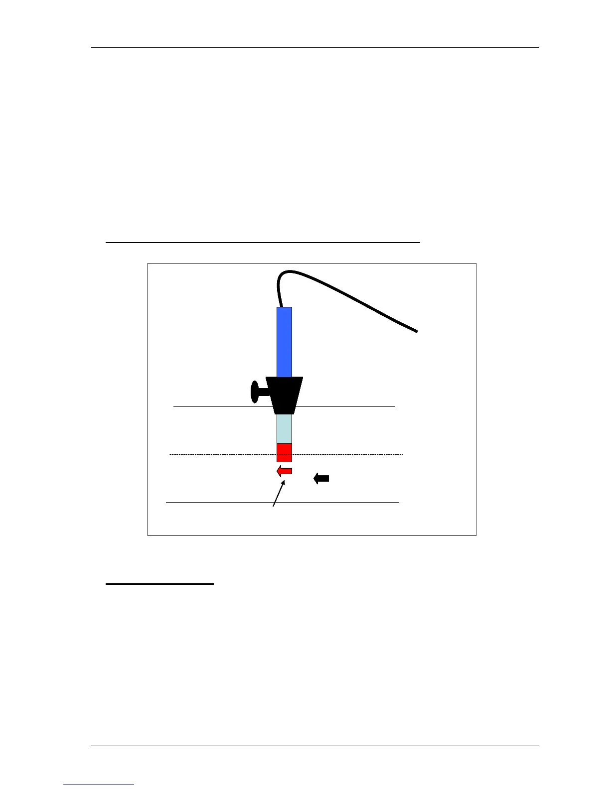
The anemometer must fit centrally (the conical fitting must be set on the probe to half the
pipe ID before insertion). The arrow on the tip of the probe must point in the direction of
the gas flow.
Note: Use the thumb screw to help align the direction of the probe into the gas
stream.
Flow readings are most accurate when there is laminar flow (not turbulent). Turbulence
can be caused by a change in pipe direction or restriction. Ideally, upstream you want at
least 20 times the pipe ID along the length of the pipe without restriction or bend.
Downstream, you want at least five times the pipe ID along the length of the pipe i.e. for a
100mm ID you need 2000mm of clear pipe upstream, 500mm downstream.
Example to show anemometer fitting into the sample point:
Instructions for use:
1) Attach the anemometer to ‘Connector C’ (refer to section 5.3 – Instrument
connection points).
2) Place the anemometer into the pipe (sample point) ready to take the reading.
3) To take a flow measurement when using an anemometer, follow the instructions
displayed on the analyser. When the reading has stabilised press the ‘Enter’ key to
store the reading.
Note: The use of an anemometer overrides internal flow.