General description 14
Code no. 550038
Rev. no. 16/1018
1.2. Machines with gas heating. Diagram and description of the burner
1.2.1. Atmospheric burner
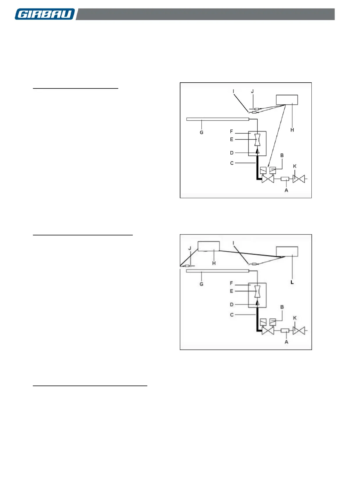
Diagram of the burner (Fig. 1.1)
A .......... Filter
B .......... Solenoid valve
C .......... Flexible section
D .......... Injector
E .......... Venturi pipe
F .......... Primary air filter
G ......... Burner
H .......... Control system
I ........... Ignition electrodes
J .......... Ionisation electrode
K .......... Manual stop-valve
Diagram of the AGA burner (Fig. 1.2)
A .......... Filter
B .......... Solenoid valve
C .......... Flexible section
D .......... Injector
E .......... Venturi pipe
F .......... Primary air filter
G ......... Burner
H .......... Control system
I ........... Ignition electrodes
J .......... Ionisation electrode
K .......... Manual stop-valve
L .......... Ignition transformer
Description of operation (Fig. 1.1 and 1.2)
When the ironer control requests heating, the burner control system (H) subjects the ignition electrodes (I) to a
high voltage for a limited time to produce an electrical discharge; while power is simultaneously fed to the
solenoid valve (B) to open the gas flow.
The gas enters the burner via a single nozzle (D).
The ionisation electrode (J) detects the flame.
If the presence of a flame has not been detected after a certain time following the ignition order, the solenoid
valve is closed, an alarm report is issued and the burner control enters safety mode.
See Section 1.6. Safety and control elements.
 Loading...