Repair
3A6748B 51
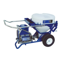
6. Reference Wiring Diagrams, page 82.
Disconnect mode switch (yellow and
black), transducer, potentiometer, amp
switch, LED display filter board (black,
blue). Remove front cover.
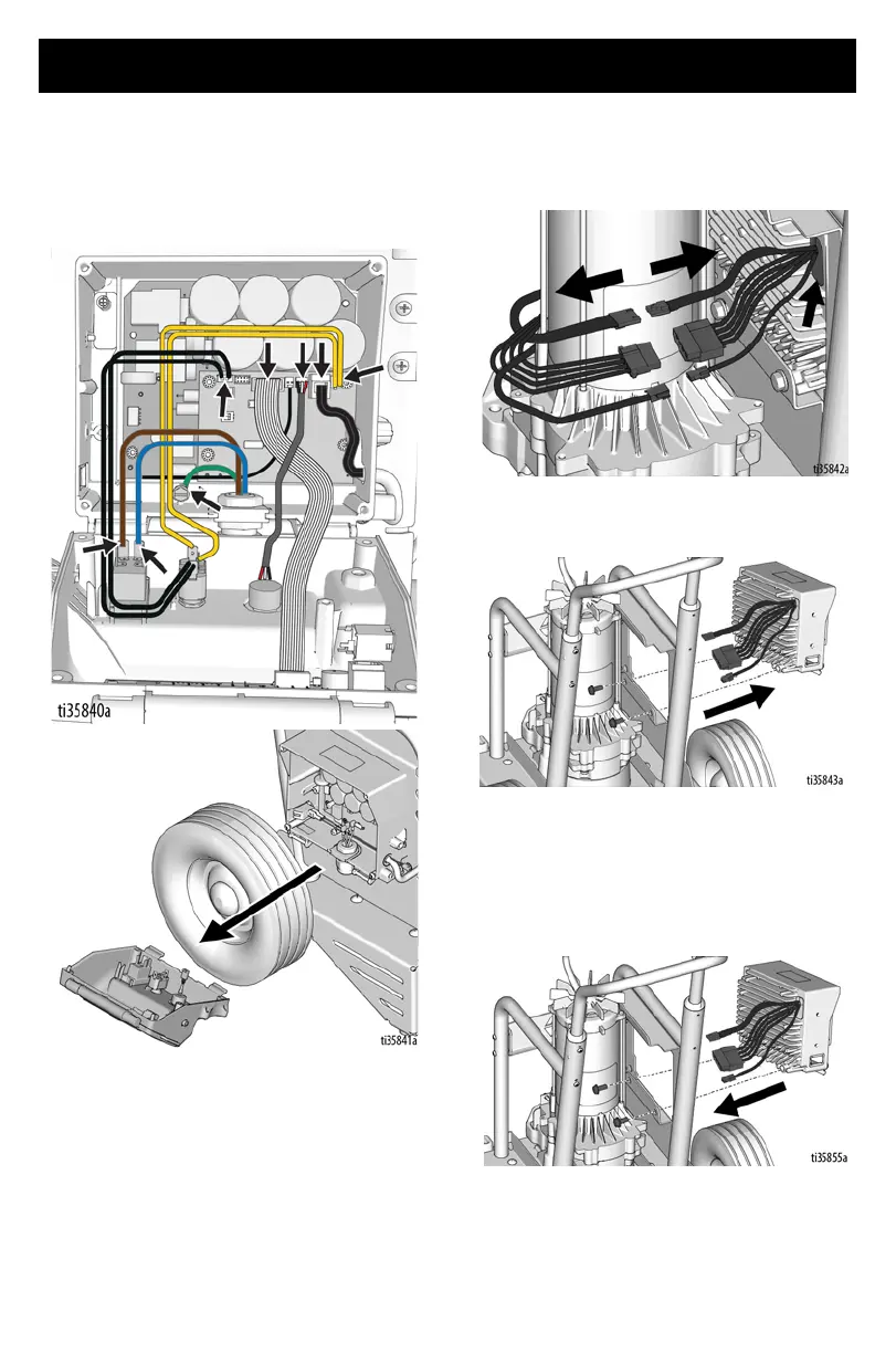
7. Disconnect motor leads, thermal switch,
and motor hall/encoder sensor. Remove
grommet.
8. Remove two screws from back of control
box and remove box.
Control Board Installation
6912
1. Install control box with two screws.