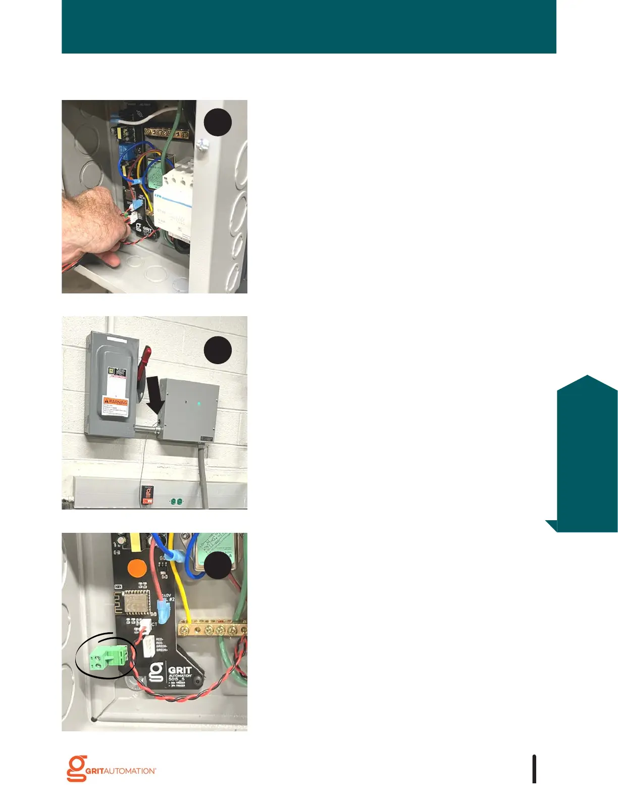
TRIGGERS
Plug the LED indicator light harness (attached to the
lid) into the PCB.
Cut, strip, and land low-voltage wire(s) into the low-
voltage terminal located on the PCB.
To power an RFiD device from an Industrial Trigger,
insert the black push-in cable connector into a small
knockout.