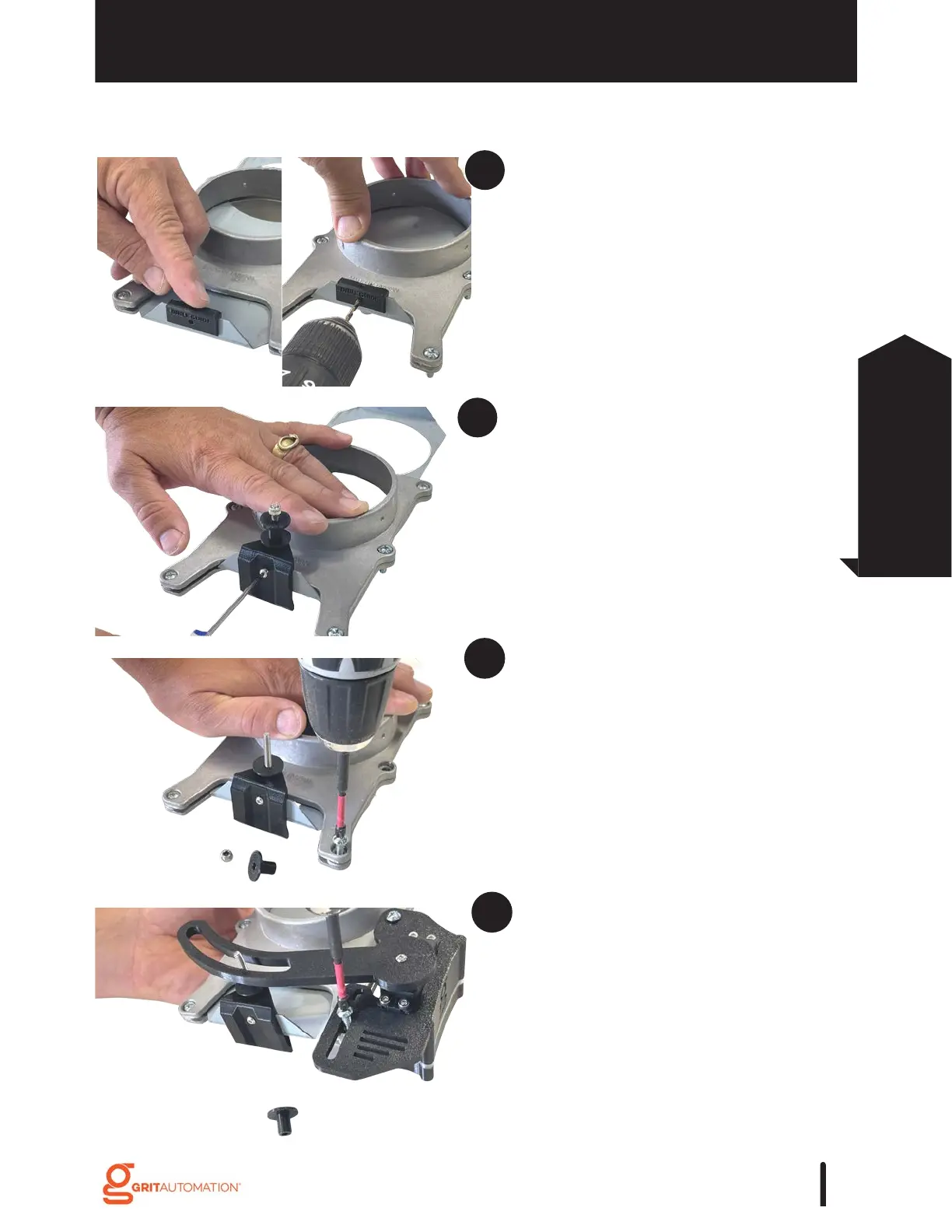
To mount the Slide Bracket to the gate’s
tab, place the Drill Guide over the
middle of the tab. Drill through the tab
with the supplied 1/8'' drill bit. Remove
the Drill Guide.
*Note: Use a new Drill Guide for each
gate.
Place the Slide Bracket over the tab,
align the holes, and screw in the M3 x
5mm screw to secure the Slide Bracket.
Remove the lock nut and hat washer
from the Slide Bracket post and remove
the two screws from the blast gate (as
seen in the picture).
Place the Arm over the Slide Bracket
and attach the Gate Actuator to the blast
gate with the provided #10-24 mounting
screws.
Installation
83
Gate Control
Installation