Published 08-25-09, Control # 077-04 2-73
RT9130E SERVICE MANUAL HYDRAULIC SYSTEM
4. Install the low temperature o-ring and backup rings onto
the outside of the head.
5. Install the cylinder head onto the cylinder rod.
6. Install the spacer onto the cylinder rod.
7. Install the o-ring and backup rings into the inside of the
piston.
NOTE: Use a new self-locking soft-tip setscrew.
8. Screw the piston onto cylinder rod and secure with a
new setscrew.
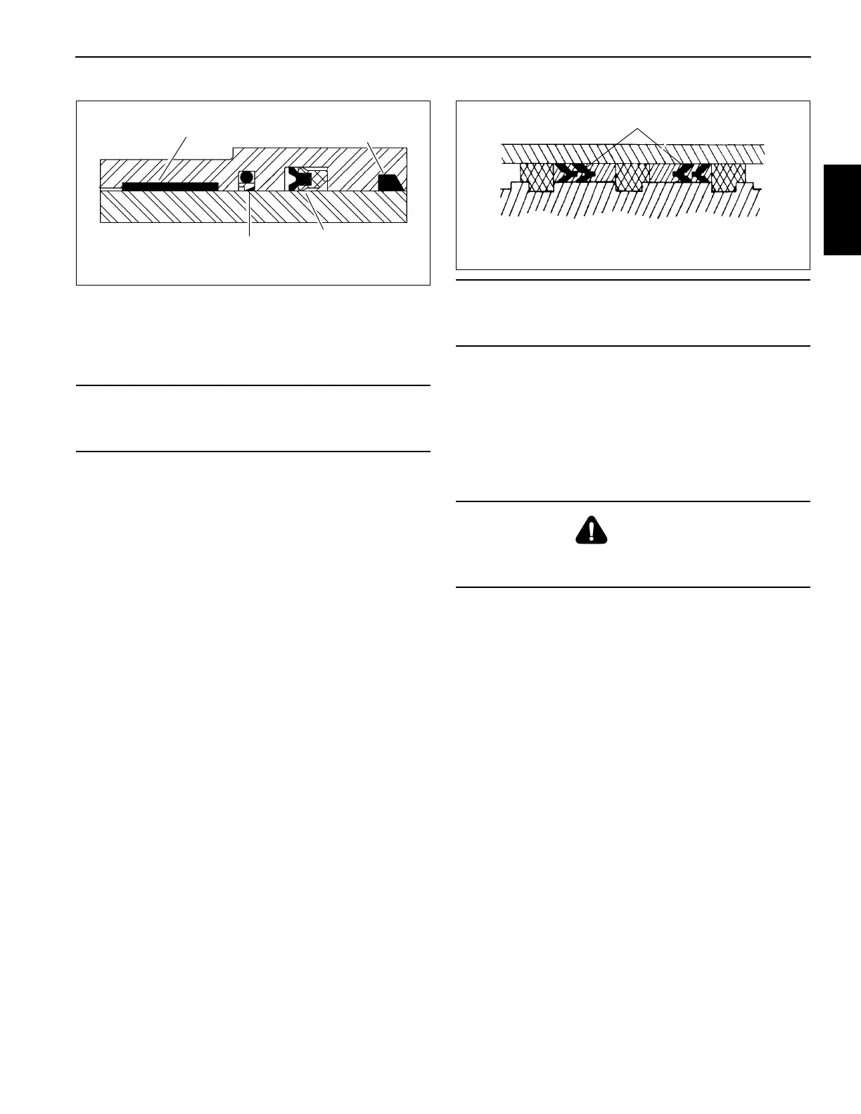
9. Install the guide lock rings and hydrolock seals onto the
outside of the piston. Refer to (Figure 2-43).
10. Clean all oil from the threads of the cylinder head and
apply Loctite #290 to the threads.
11. Lubricate the piston seals and cylinder head o-ring with
clean hydraulic oil and install the rod assembly into the
cylinder barrel with a slight twisting motion.
12. Using a chain wrench, secure the cylinder head to the
cylinder barrel.
13. Pressurize and cycle the cylinder with hydraulic oil
pressure. Test the cylinder at 36197.4 kPa/36.1 bar
(5250 psi) retracted (rod side pressure) or 25855.3 kPa/
25.8 bar (3750 psi) extended (piston side pressure).
Check for proper operation and any leakage. Make
repairs as needed.
CAUTION
Improper seal installation could cause faulty cylinder
operation.
Wiper Ring
Deep Z Rod Seal
Buffer Seal
Wear Ring
FIGURE 2-42
CAUTION
Do not scratch the grooved and gland surfaces or
damage the seals and o-rings.
DANGER
Do not use air pressure to cycle the cylinder. Use only
controlled hydraulic pressure.
Hydrolock Piston Seals
FIGURE 2-43