Published 08-25-09, Control # 077-04 4-51
RT9130E SERVICE MANUAL BOOM
At the front of the 8 m sections there are two quick couplings
(1) (Figure 4-16).
Here you can connect the hydraulic hoses of the 11 m
section or a second 8 m section.
Electrical Connection On the Boom
Extension
This section describes the electrical connections on the 8 m
sections.
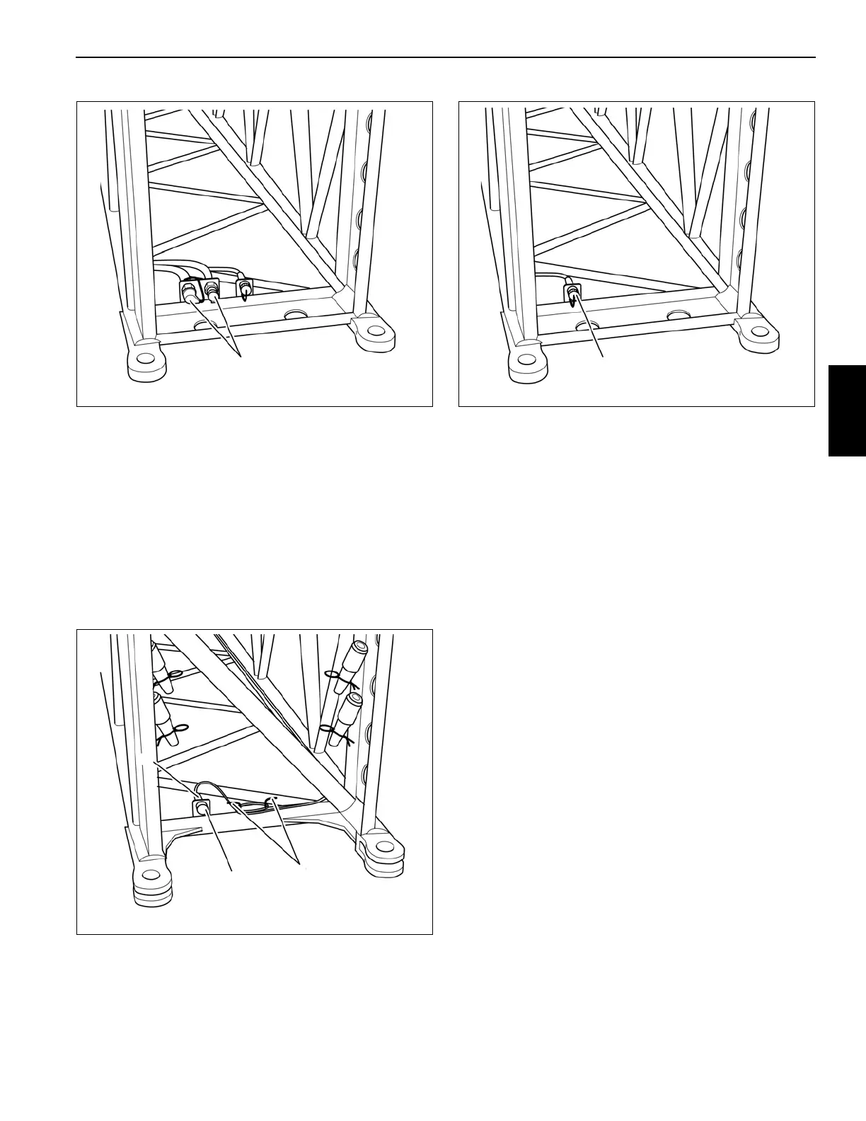
Connections On the 8 m Sections
At the rear of the 8 m sections there is a cable with a plug (3)
(Figure 4-17).
For transportation, the cable is wound around the holders (1)
and the plug is inserted in the dummy socket (2)
(Figure 4-17).
At the front of the 8 m sections there is a plug socket (1)
(Figure 4-18).
Here you can connect the cable of the 11 m section or a
second 8 m section.
Establishing Electrical Connections
For the 26 m Boom Extension
• Connect the cable of the 8 m section to the socket on the
main boom head.
• Connect the cable of the 11 m section on the socket at
the front of the 8 m section.
For the 34 m boom extension
• Connect the cable of the first 8 m section to the socket
on the main boom head.
• Connect the cable of the second 8 m section to the
socket at the front of the first 8 m section.
• Connect the cable of the 11 m section on the socket at
the front of the second 8 m section.
Folding Out/In the Deflection Sheaves On
the 8 m Sections
This section describes only the folding in and out of the
deflection sheave on the 8 m section.
If you intend to work with the boom extension, you need to
fold out the deflection sheaves on the rear 8 m sections.
Fold the deflection sheave in for transportation.