2-22 Published 08-25-09, Control # 077-04
HYDRAULIC SYSTEM RT9130E SERVICE MANUAL
Procedure B - For Checking Pressure
Reducing/Sequence Valve Setting
Procedure for Checking Sequence Valve Setting (see
(Figure 2-8)
1. Remove cap and install pressure gauge on the
outrigger/rear steer valve pressure test port
(Figure 2-15).
2. With the engine running at idle, adjust the sequence
valve cartridge to 8.6 +0.4/-0 MPa (1250 +50/-0 PSI). If
adjustment is required, use a shim with an outside
diameter 0.56 inch, an inside diameter of 0.375 inch,
and a thickness of 0.06 inch to increase pressure about
50 PSI.
3. Remove pressure gauge from the Outrigger/Rear Steer
Valve Test Port and reinstall cap.
Procedure for Checking Hose Reel Motor and Hose
Reel Brake Pressure Reducing Valve Setting
(Figure 2-8)
1. Remove cap and install pressure gauge on the hose reel
brake and motor test port (Figure 2-8).
2. With the engine at full RPM, adjust the hose reel motor
and brake pressure reducing valve cartridge to 8.3
± 0.4
MPa (1200
± 50 PSI).
3. Remove pressure gauge from the test port and reinstall
cap.
Procedure for Checking Controller Supply Pressure
Reducing Valve Setting (Figure 2-8)
1. Remove cap and install pressure gauge on the controller
supply test port.
2. With the engine running at full RPM, adjust the controller
supply pressure reducing valve cartridge to 2.8
± 0.4
MPa (400
± 50 PSI) (Figure 2-8).
3. Remove pressure gauge from the test port and reinstall
cap.
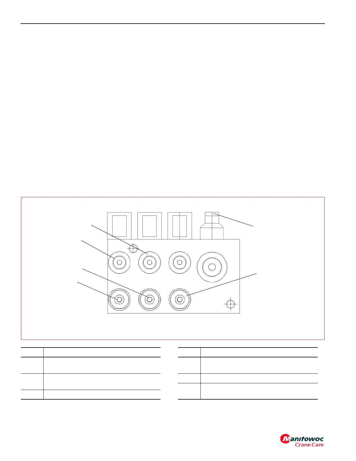
Pressure Reducing Sequence Valve Assembly
6098
FIGURE 2-8
1
2
3
4
5
6
Item Description
1
Hose Reel Brake and Motor Pressure
Reducing Valve Adjustment
2
Controller Supply Pressure Reducing Valve
Adjustment
3 Controller Supply Test Port “REG 1”
Item Description
4
Hose Reel Brake and Motor Test Port “REG
2”
5 Sequence Valve Cartridge
6
Swing Brake Supply Pressure reducing valve
adjustment