Published 08-25-09, Control # 077-04 4-47
RT9130E SERVICE MANUAL BOOM
BOOM EXTENSION (WITH INSERTS)
Identification
The boom extension consists of the 18 m two-stage
swingaway lattice extension and two boom extension
sections. The boom extension is designed for the crane it
was delivered with. The parts belonging to the crane have
the same serial number as the crane.
The following parts are labelled with the serial number:
• all parts of the 128 m two-stage swingaway lattice
extension
• both sections of the boom extension (8 m sections)
NOTE: For technical reasons a crane may only be set with
one boom extension.
If you wish to use the boom extension on several GROVE
cranes, the parts of the boom extension must be adjusted for
these cranes and labelled with all of the respective serial
numbers.
Serial Numbers On the 8m Sections
On the 8 m sections the serial number (1) is at the front on a
sheet (Figure 4-9).
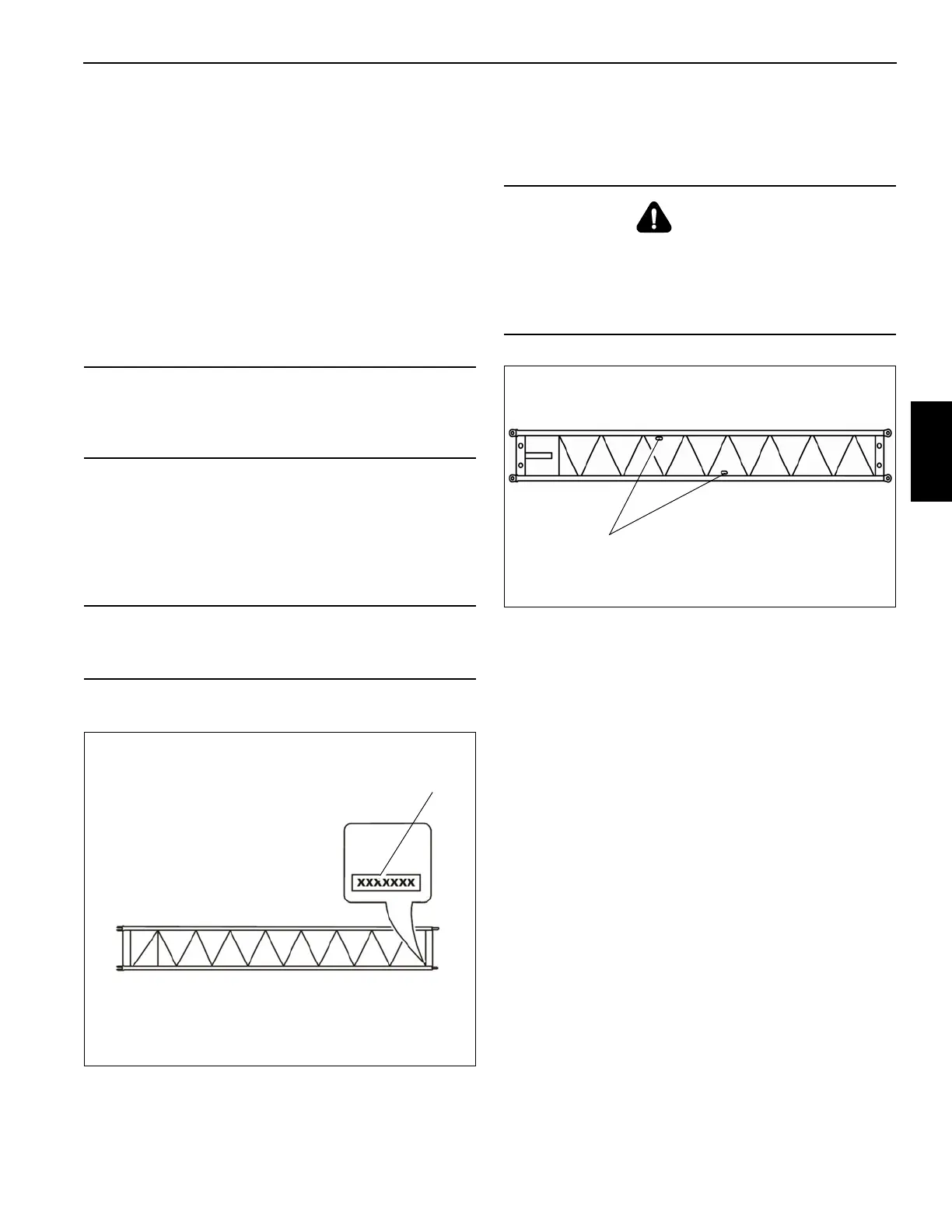
Slinging Points
The 8 m sections have two slinging points (1) (each slightly
offset on each side) (Figure 4-10).
ASSEMBLY OF BOOM EXTENSIONS
NOTE: The lengths of 26 m and 34 m respectively equal
the distance between the center of the locking pin
(on the main boom head) and the front edge of the
head sheave.
The designations 11 m section, 7 m section and 8
m section have been adapted top these lengths.
The total lengths of the individual sections are
greater (Figure 4-11).
CAUTION
Operate the crane only with those sections of the boom
extension which have the same serial number as the
crane. This prevents malfunctions and damage.
CAUTION
Have the adjustment of the boom extension carried out
only by your local Manitowoc Crane Care.
DANGER
This section shows the slinging points on the 8 m
sections. Attach the sections on these slinging points only.
They will then automatically have the correct center of
gravity. use only lifting gear with sufficient load bearing
capacity.