Published 08-25-09, Control # 077-04 3-11
RT9130E SERVICE MANUAL ELECTRICAL SYSTEM
Check
1. Try to start the engine. Verify the starter starts the
engine.
2. Start engine again, and listen for starter noises. Verify
there is no abnormal noise indicating the starter’s gear is
meshing improperly with the flywheel, that the starter’s
gear hasn’t disengaged from the flywheel after the
ignition switch is in the ignition. (run) position, or some
other problem. Install starter properly as needed.
Battery Replacement
Removal
1. Open the battery box cover.
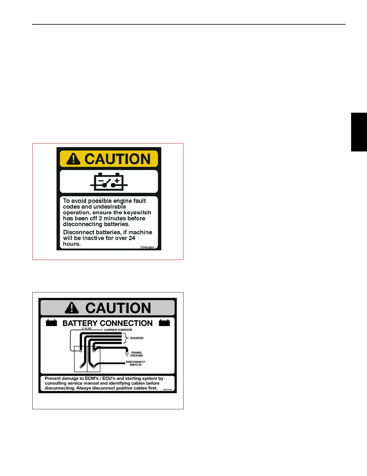
2. Tag and disconnect leads from the battery terminals
starting with the positive terminals (Figure 3-10).
3. Remove the nuts and washers from the bracket hold
down rods. Remove the hold down bracket.
4. Remove the batteries.
Installation
1. Place the batteries in the battery box.
2. Install the hold down bracket so it can hold down the
batteries. Secure the bracket (and batteries) to the
bracket hold down rods with nuts and washers.
3. Connect leads to the battery terminals starting with the
negative terminals.
4. Close the battery box cover.
5. Verify replacement batteries work by starting crane’s
engine and operating various crane components.
Relay Panel Component Replacement
Accessory Relay
1. Disconnect the batteries.
2. Remove the hardware securing the console front cover
and remove the cover.
3. Tag and disconnect the electrical leads from the suspect
relay.
4. Remove the hardware securing the suspect relay to the
relay panel assembly. Remove suspect relay.
5. Install replacement relay on relay panel and secure it
with attaching hardware.
6. Connect the electrical leads to the relay as tagged
during removal.
7. Position the console front cover on the console and
secure with the attaching hardware.
8. Connect the batteries.
9. Verify proper installation by operating all components
involved with the replacement relay verifying they all
work.
Buzzer Replacement
1. Remove the hardware securing the console front cover
and remove the cover.
2. Tag and disconnect the electrical leads from the buzzer.
3. Unscrew the plastic collar ring from under the panel and
remove the buzzer from the hole in the panel.
4. Install replacement buzzer through the hole in panel and
secure with the plastic collar ring.
5. Connect the electrical leads to the buzzer as tagged
during removal.
6. Position the console front cover on the console and
secure with the attaching hardware.