Published 08-25-09, Control # 077-04 3-1
RT9130E SERVICE MANUAL ELECTRICAL SYSTEM
SECTION 3
ELECTRICAL SYSTEM
DESCRIPTION
General
The electrical system is 12-volt operation with 12-volt
starting, consisting of an alternator and two lead-acid
batteries. The system is the single wire ground return type,
using the machine’s structure as ground.
Electrical power is transferred to and from the carrier and
superstructure through the electrical swivel. For more
detailed information on the electrical swivel, refer to Section
6- SWING SYSTEM.
The superstructure control module is located behind the front
console in the cab and the carrier control module is located
near the hydraulic oil tank.
Alternator
The alternator (Figure 3-1) is mounted on the engine and is
belt driven. It is a 130 ampere alternator with an integral
transformer - rectifier unit. When the engine is running, and
the alternator is turning, the alternator’s 12-volt output
terminal supplies the crane’s electrical circuits. The output
terminal also supplies the voltage to recharge the batteries
and maintains them at a full state of charge.
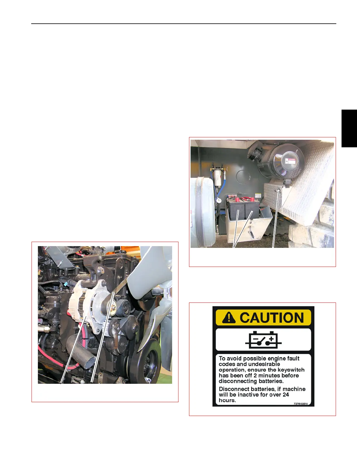
Batteries
The batteries (Figure 3-2) are located in a box on the left side
of the crane behind the fuel tank. Each battery is the
maintenance free type and is completely sealed except for a
small vent hole in the side. The vent hole allows what small
amount of gases that are produced in the battery to escape.
On some batteries, a test indicator located on the top of the
battery is used to determine if the battery can be tested in
case of a starting problem.
A battery disconnect switch is located on the right side of the
battery box (Figure 3-2).To disconnect the batteries, turn the
battery disconnect switch to OFF. Turn the switch to ON to
connect the batteries. Observe the Caution in (Figure 3-3)
FIGURE 3-1
7333-5
Alternator Alternator Belt
FIGURE 3-2
7333-1
Batteries Battery Disconnect Switch