3-6 Published 08-25-09, Control # 077-04
ELECTRICAL SYSTEM RT9130E SERVICE MANUAL
continuity through its coil, replace the relay. Make circuit
repairs to accessory control circuit as needed.
4. If the problem remains, check the accessory relay K1 or
K2 contacts and the accessory power circuit. Replace
relay if its contacts stay open when the coil is energized.
Make circuit repairs as needed.
Troubleshooting Swivel-Caused Electrical
Problems
Many crane component electrical troubles can be traced to
the electrical swivel. Troubles common to the swivel are
improper mounting, foreign material between the brushes
and slip rings, incorrect wiring from the swivel to the
components, incorrect wire size, worn brushes, improper
spring tension on the brush assembly, and loose setscrews
on the slip ring assembly. Refer to the electrical schematic
and wiring diagram for slip ring connections and amperages.
Connector Troubleshooting
The cause of an electrical problem may be a loose or
corroded connection in the pin or socket connectors. Check
the connectors to ensure that the pins and sockets are
properly seated and engaged. If the pins and sockets show
any signs of corrosion, use a good quality electrical contact
cleaner or fine sandpaper to clean them. When the pins or
sockets show signs of arcing or burning, it will probably be
necessary to replace them.
After cutting the pin or socket off, the wire will most likely be
too short. Using a wire that is too short will allow pressure to
be applied to the pin or socket and wire where they are
crimped when the pin or socket is inserted in the plug or
receptacle. Add a short length of the same size wire to the
short wire by crimp splice or solder. Use heat shrinkable
tubing or other suitable material to insulate the splice.
Table 3-2
Deutsch Extraction Tool Table
Table 3-3
Deutsch Crimping Tool Table
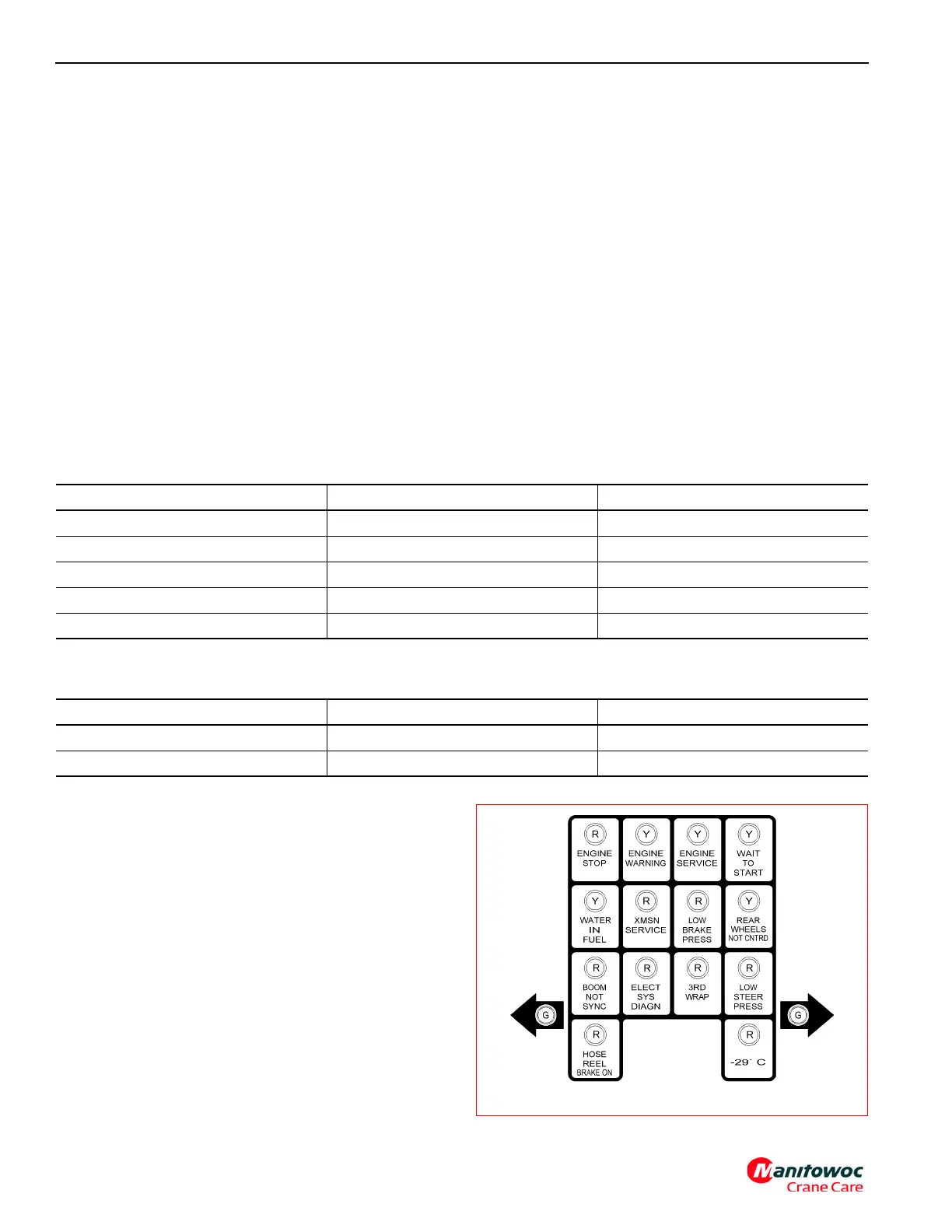
Indicator Lights and Diagnostic Light
The front console indicator lights (Figure 3-8) are located in
the cab on the center of the front console. The lights are
linked to various parts of the crane by the control module and
notify the operator when a certain condition occurs during
the operation of the crane. When the ignition key is turned to
the ACC or RUN position the indicator lights go through all
operations check to see if the lights are working. This
operation check takes about two seconds in which all of the
lights except for the Hoist Third Wrap and Low Steer
Pressure (as applicable) lights turn on and off allowing the
operator to know that the lights are working. For more
description on the front console indicator lights, refer to
Section 3 in the Operator’s Manual
Description Deutsch Part Number Grove Part Number
12 gauge wire 114010 9-999-100194
16 gauge wire 0411-204-1605 9-999-100195
8-10 gauge wire 114008 7-902-000012
4-6 gauge wire 114009 7-902-000009
20-24 gauge wire 0411-240-2005 9-999-102084
Description Deutsch Part Number Grove Part Number
12, 14, 16, 18, 20, 22, 24 gauge wire HDT-48-00 9-999-100808
4, 6, 8, 10 gauge wire HDT04-08 9-999-100842