Published 08-25-09, Control # 077-04 5-15
RT9130E SERVICE MANUAL HOIST AND COUNTERWEIGHT
HOIST DRUM ROTATION INDICATOR
SYSTEM
Description
The hoist drum rotation indicator system is an electrically
operated system that provides the operator with a touch
indication of drum rotation so he will know if and at what
speed the hoist drum is rotating, even under the most
distracting conditions.
The rotation indicator system consists of three separate
electrical components; the rotation indicator sensor, drum
rotation indicator control module (CPU), and thumb thumper
solenoid. The rotation sensor and control module (CPU) are
located on the hoist. The pulsing thumb thumper solenoid is
located in the applicable hoist control lever handle.
Maintenance
General
Proper circuit operation can be checked for each individual
electrical component. If a malfunction occurs within the
system, repairs should be limited to finding and replacing the
faulty component(s). To determine which component is at
fault, use the self diagnostic LEDs on the CPU. If difficulty
persists, contact your local dealer for additional
troubleshooting aid.
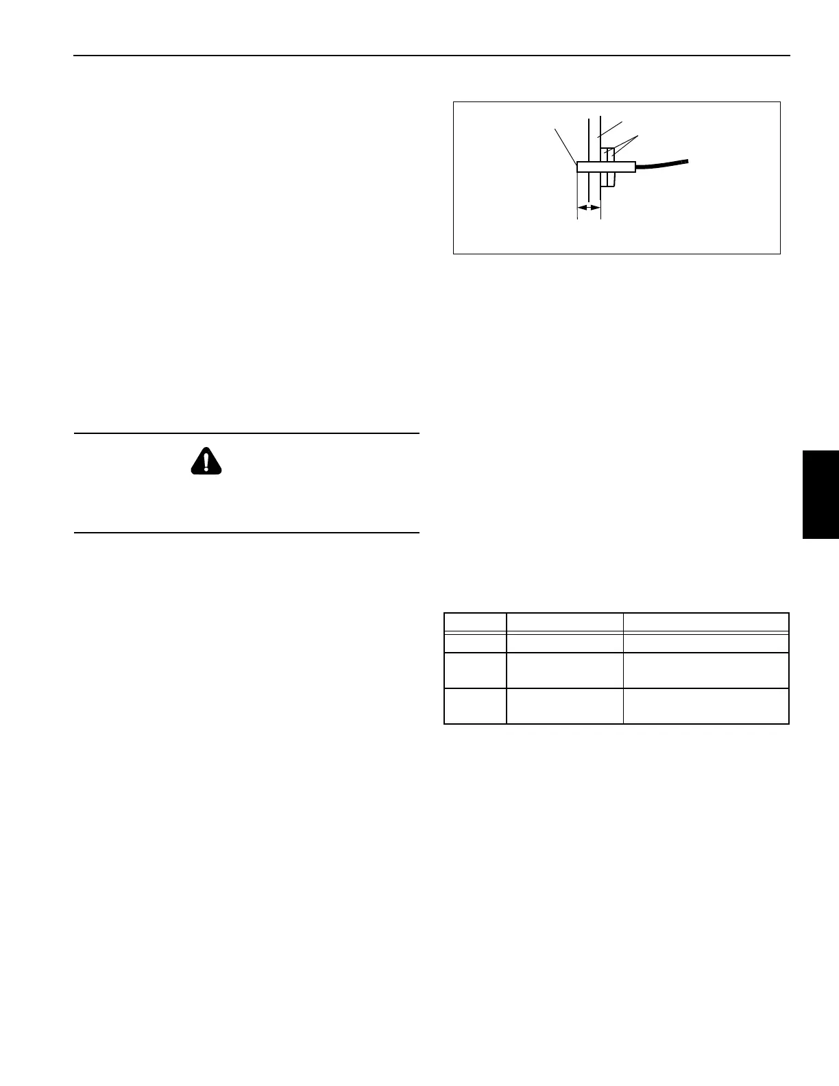
Rotation Sensor
The rotation sensor is screwed into the hoist support end
bracket that holds the hydraulic motor (Figure 5-5). It senses
the rotation of the drum. When installing the sensor, ensure
its sensing end is 1.21 inch (31 mm) from the first lock nut.
(This is the length of the sensor from its sensing end through
to the outside surface of the hoist support end bracket.) If
sensor will not work properly, loosen both lock nuts and turn
the sensor counterclockwise up to one turn, then retighten
lock nuts to hold sensor position. If sensor will still not work
properly, ensure its sensing end is 1.21 inch (31 mm) from
the first lock nut, then turn the sensor clockwise up to one
turn, then retighten lock nuts to hold sensor position.
Drum Rotation Indicator Control Module
(CPU)
The control module (CPU) is bracket mounted to the upper
hoist motor attaching bolt. It provides LEDs for checking
proper circuit operation, as well as providing power to the
rotation sensor. It also sends a signal to the thumper
solenoid proportional to the sensor.
Thumb Thumper Solenoid
The thumb thumper solenoid provides feedback proportional
to the hoist line speed by pulsing the rubber button on top of
the hoist control lever.
Troubleshooting
To troubleshoot the system, use the three diagnostic LEDs
located on the control module (CPU). Under normal
operating conditions (hoist drum rotating) the diagnostic
LED’s function as shown in the following table.
Table 5-2
NOTE: The following paragraphs troubleshoot the system
using the diagnostic LEDs. The hoist drum must be
rotating during all troubleshooting.
Green LED
Turn the ignition switch on. Verify that the green LED is on.
The LED should stay on as long as accessory power is on. If
the green LED is not on, either the voltage did not arrive at
the CPU, or the CPU is defective and needs to be replaced.
If the green LED repeatedly flashes once with the red and
yellow LEDs off, the solenoid circuit is shorted. If the green
LED repeatedly flashes two times with the red and yellow
LEDs off, the CPU is defective. If the green LED repeatedly
flashes three times with the red and yellow LEDs off, the
DANGER
Disconnect the batteries before performing any
maintenance on this system. Serious burns may result
from accidental shorting or grounding of live circuits.
LED OPERATION DEFINITION
Green On continuously Current applied to sensor
Red
Pulses on, varies
with speed
Sensor signal received
Yellow
Pulses on, varies
with speed
Solenoid pulse working
Support End Bracket
1.21 in. (31 mm)
Lock Nuts
Sensing End
FIGURE 5-5
7068