BOOM RT9130E SERVICE MANUAL
4-46 Published 08-25-09, Control # 077-04
1. Disconnect the hoses from the lattice extension from the
drum hoses. Do not detach the drum hoses from the
boom nose.
When working with the main boom for longer periods of time,
the hydraulic connection between the hose drum and the
boom nose should be disconnected. This prevents
unnecessary reeling and unreeling of the hose.
2. Remove the hoses from the boom nose. Retract the
hydraulic hoses to the holder on the boom base section.
3. Engage hose drum lock pin into hole on drum.
4. Wind the hoses onto the boom extension for storage.
5. Install dust caps attached to all couplings on the lattice
extension and the drum hoses.
Swingaway Mounting Adjustment
For the referenced details, refer to (Figure 4-7).
1. Set the 11 m section with the 7 m section stowed on the
side, on cribbing. Use an adequate lifting device to place
the boom extension at the side of the boom. Make the
connection at the front stowage bracket and support with
lifting device (Detail A) (Figure 4-7).
2. Refer to Detail A (front stowage bracket) and pivot the
boom extension on the front support bracket. Adjust the
front support bracket adjustment bolts to maintain a
loose condition when the boom extension anchor fittings
engage the boom anchor lugs.
3. Secure the guide rail on the middle boom extension
stowage bracket in the out position.
4. Swing the boom extension until it contacts the guide rail
at the middle boom extension stowage bracket (Detail B)
(Figure 4-7).
NOTE: When pushing the jib extension onto the guide rail,
make sure contact does not occur at the rear boom
extension mounting bracket and prevent proper
alignment.
5. Adjust the middle stowage bracket so the roller supports
on the 11 m section role on the guide rail and aligns the
roller support on the 7 m section. This should align the
hole in the mounting lug on the 7 m section with the hole
in the mounting piece on the stowage bracket. When
adjusted properly, the pin can be inserted to make the
stowage connection.
6. Refer to (Detail C) (Figure 4-7) (rear stowage bracket)
and adjust the adjustment bolts on the rear support
bracket to support the boom extension and provide
installation of attach pins.
7. Remove the lifting device used for support when the
boom extension is secured.
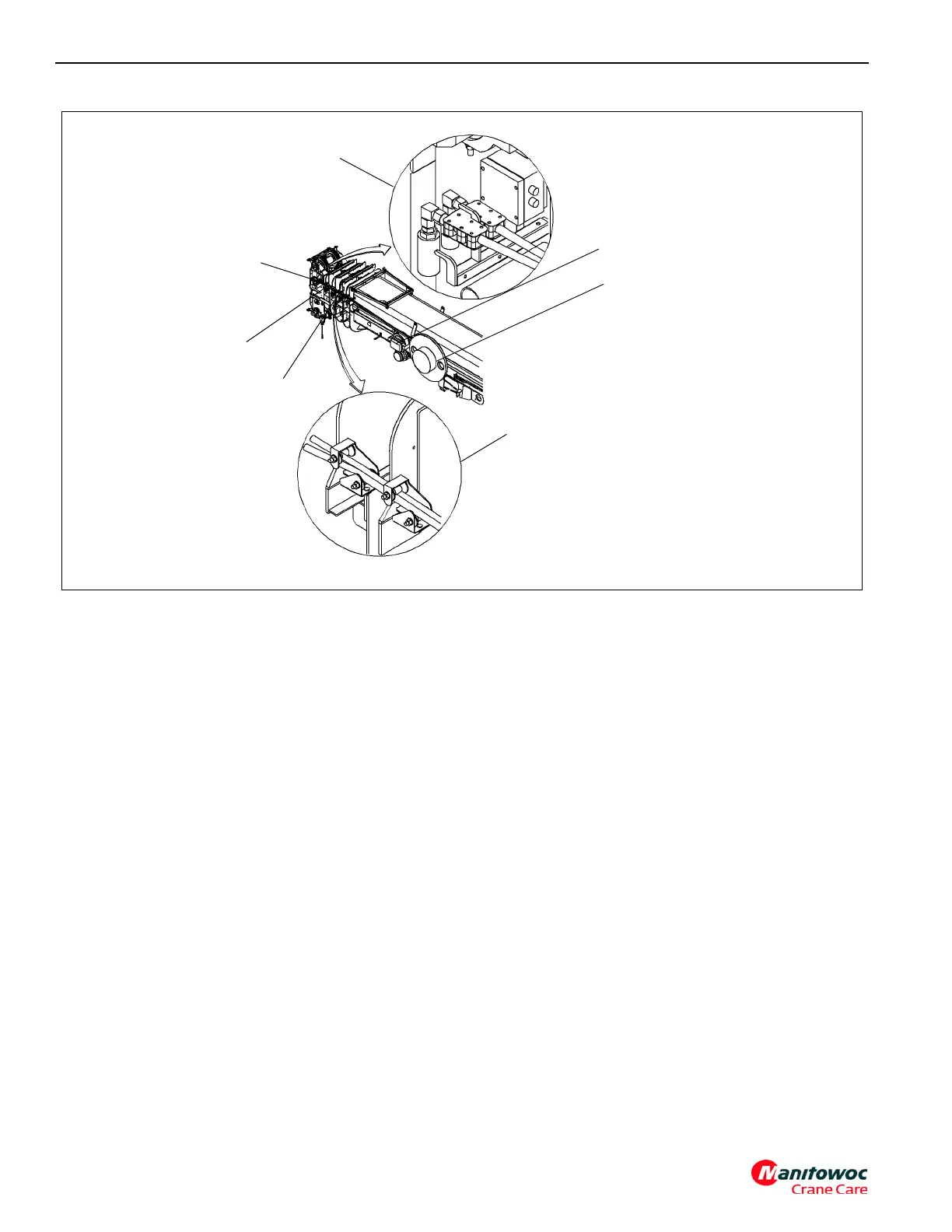
Junction Box
17-Pin Bypass
Connector
6218
FIGURE 4-8
Junction Box Assembly
Hose Drum
Boom Nose Holder
Guide Rollers
Guide Rollers