Published 08-25-09, Control # 077-04 2-27
RT9130E SERVICE MANUAL HYDRAULIC SYSTEM
6. Disconnect the couplers for the counterweight pin from
the cylinder located at the rear of the turntable. DO NOT
PERFORM THIS TEST IF THE COUPLERS ARE
CONNECTED TO EITHER THE COUNTERWEIGHT
PIN CYLINDER OR THE BOOM PIVOT CYLINDER!
Operate the counterweight pin lever to retract. Adjust the
counterweight pin “B” port relief to 17.2
± 0.4 MPa (2500
± 50 PSI).
7. Operate the counterweight pin lever to extend. Adjust
the counterweight pin “A” port relief to 17.2
± 0.4 MPa
(2500
± 50 PSI). Connect the couplers to the
counterweight pin cylinder.
8. Remove gauge and reconnect plumbing.
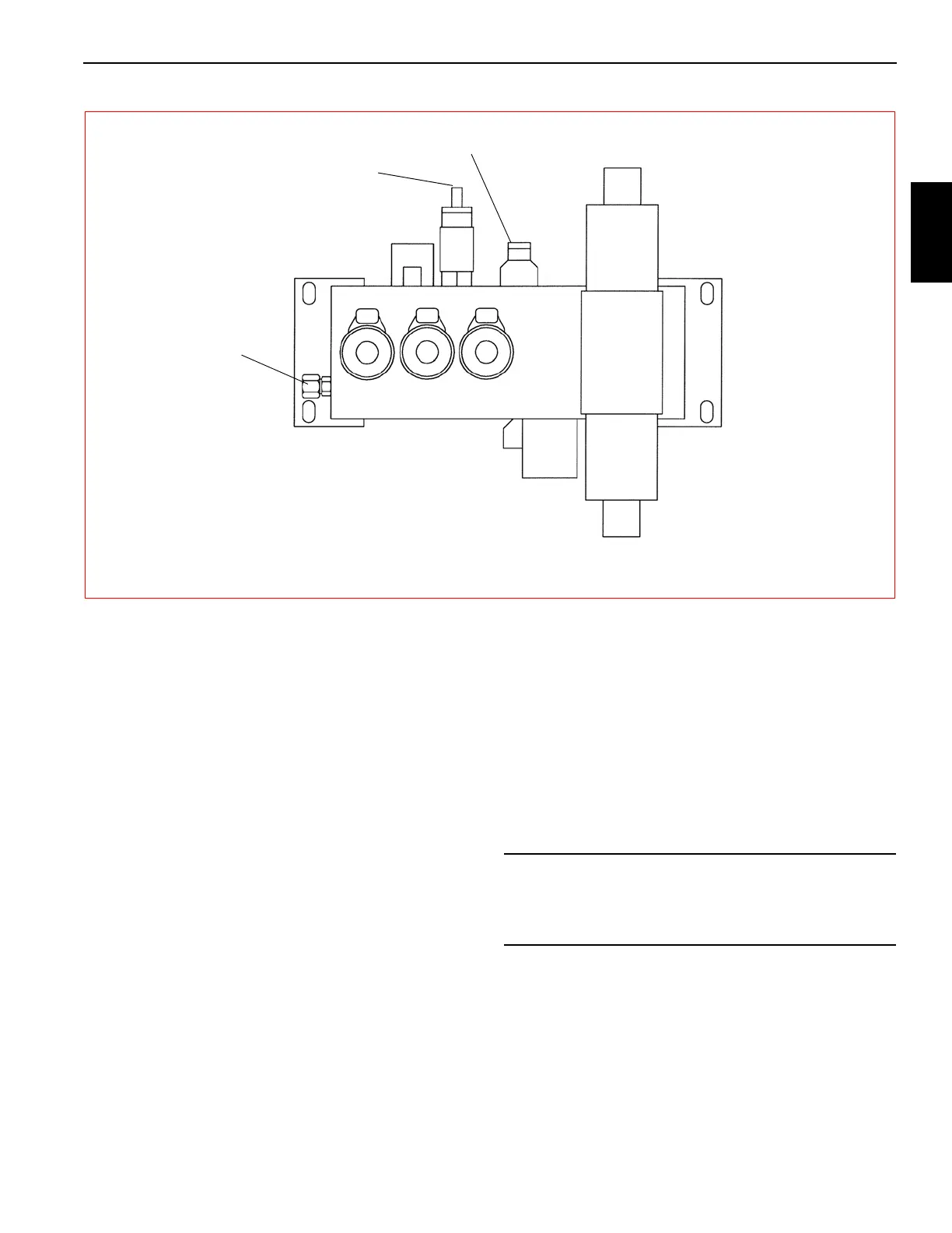
Procedure K - For Checking Outrigger/Rear
Steer Relief Valve Pressure
1. Remove cap and install pressure gauge (Figure 2-15)
on outrigger/rear steer valve pressure check port.
2. With engine running at full RPM, fully extend one
outrigger beam. Adjust the sequence relief valve to 13.8
± 0.4 MPa (2000 ± 50 PSI). If adjustment is required,
remove socket head plug from end of cartridge. Adjust
internal socket head plug in (CW) to increase pressure
or out (CCW) to decrease pressure. When complete,
reinstall socket head plug into end of cartridge.
3. With the engine running at full RPM, fully extend one
outrigger stabilizer. Adjust the outrigger two stage relief
valve to 24.2
± 0.4 MPa (3500 ± 50 PSI). If adjustment is
required, loosen locknut and use 1/4 inch Allen wrench
to turn adjustment screw in (CW) to increase pressure or
out (CCW) to decrease pressure. When complete,
tighten locknut.
4. Remove pressure gauge from outrigger/rear steer valve
and reinstall cap.
Procedure L - For Setting Hoist Motor
Control Valve
1. Remove SAE #4 plug on the top side of the hoist valve
block (hoist brake release) (Figure 2-7) and install
pressure gauge.
2. With engine at idle RPM, very slowly meter into the hoist
DOWN direction while monitoring the brake valve
opening pressure. The gauge should read 3.8 - 4.5 MPa
(550 - 650 PSI); adjust as required.
3. Remove pressure gauge and reinstall SAE #4 plug.
FIGURE 2-15
Pressure Check
Sequence Relief Adjustment
Outrigger/Rear Steer Valve
7128-5
Outrigger Valve Adjustment
CAUTION
This procedure should only be performed if the hoist is
rough (chatter, jumpy, or unstable load). Omit if hoist
operation is acceptable.