Published 08-25-09, Control # 077-04 7-15
RT9130E SERVICE MANUAL POWER TRAIN
Air Cleaner Body
Before installing the filter element, remove foreign material
(leaves, lint or other foreign matter) that may have collected
inside the air cleaner body. Inspect the inside of the body for
dents or other damage that would interfere with air flow or
with the fins on the element or inside the body. Repair any
body dents, being careful not to damage the sealing
surfaces. Be sure to clean the sealing surface of the outlet
tube and the inside of the outlet tube, taking care not to
damage the sealing area on the tube.
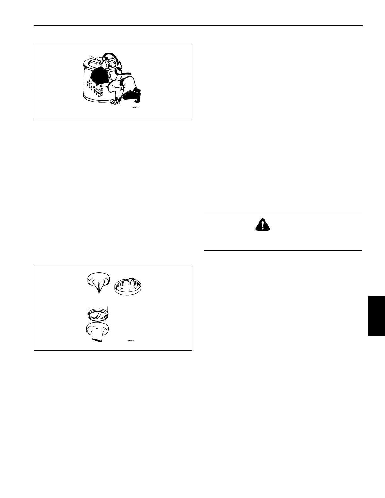
Vacuator Valve
Vacuator valves are designed to expel loose dust and dirt
from the air cleaner body automatically, thus lengthening the
element service life. The valve lips must point straight down
and be kept free from debris to operate effectively. Mud and
chaff can lodge in these lips periodically and hold them open
during engine operation (Figure 7-12).
Check the condition of the valve and lips frequently and keep
them clean. The valve lips should be open only when the
engine is shut down, or running at low idle speed. If the valve
is turned inside out, check for a clogged air cleaner inlet.
Malfunction of this valve does not reduce the air cleaner
effectiveness, but does allow the element to get dirty faster
and reduces serviceable life. If a valve is lost or damaged,
replace it with a new valve of the same part number.
Duct Work
1. Check the intake pipe cap and screen for accumulation
of leaves, trash, and other debris that could restrict air
flow. Repair the screen or replace the cap if any large
holes are found in the screen.
2. Check all mounting hardware for security to eliminate
possible vibration of intake piping. Such vibration leads
to early failure of hoses, clamps, and mounting parts,
and can cause hoses to slip off the connecting pipes,
allowing un-filtered air into the engine air intake.
3. Check hoses for cracks, chafing, or deterioration, and
replace at the first sign of probable failure.
MUFFLER
NOTE: Standard muffler and CE muffler are similar in
removal and installation (Figure 7-13) despite the
differences in the two mufflers, the exhaust
tailpipes, and the mounting bracket weldments.
Removal
1. Remove muffler clamps to free exhaust tailpipe from
muffler and muffler mounting bracket.
2. Remove seal clamp to free muffler from exhaust tube.
3. Remove mounting bands to free muffler from muffler
mounting bracket. As needed, remove capscrews and
nuts to free muffler mounting bracket from its mountings.
4. Inspect muffler, exhaust tailpipe, exhaust tubes, bracket,
and attaching hardware. Repair or replace any of these
parts if damaged or missing.
Installation
1. Secure the muffler to the exhaust tube with a seal clamp.
2. Install the exhaust tailpipe on the muffler. Secure the
exhaust tailpipe to the muffler and muffler mounting
bracket with muffler clamps. Adjust the seal clamp as
needed.
3. Secure the muffler mounting bracket to its mountings
with capscrews and nuts as needed. Secure the muffler
to the muffler mounting bracket with mounting bands.
DANGER
Do not touch muffler or exhaust parts until they are at
ambient temperature. Severe burning may result.