2-24 Published 08-25-09, Control # 077-04
HYDRAULIC SYSTEM RT9130E SERVICE MANUAL
6. Adjust the pressure until the high charge limit is 19 +0.4/
-0 MPa (2750 +50/-0 psi) and the low charge limit is
2200 to 2350 psi (15.2 to 16.2 MPa).
7. Stop the engine. Remove the pressure gauge, re-cap
the test port tee, and reinstall fittings in the tank port on
the service brake dual accumulator charge valve.
Procedure F - For Checking Accumulator
Pre-Charge Pressure
1. With the engine off, discharge all of the pressurized oil
stored in the accumulators by depressing the service
brake pedal on the cab floor several times. Remove the
gas valve guard and cap on the accumulator
(Figure 2-12).
2. Check that the nitrogen supply bottle is shut off, then
attach charging assembly hose to nitrogen bottle.
3. Before attaching the gas charging assembly
(Figure 2-12) onto the accumulator gas valve, back the
gas chuck "T" handle all the way out (counterclockwise).
4. Close the charging assembly bleed valve. Without
twisting hose, attach the swivel nut onto the gas valve
and tighten to 10-15 inch-pounds (1.1 to 1.7 Nm).
5. Crack open the nitrogen bottle valve and slowly fill the
accumulator. Shut off the valve when the pre-charge
pressure is 9.7 + 0.4/-0 MPa (1400 + 50/-0 PSI).
6. Turn the gas chuck "T" handle all the way down
(clockwise) to depress the core in the gas valve.
7. Check the pre-charge pressure. It should be 9.7 + 0.4/-0
MPa (1400 + 50/-0 PSI).
8. If the pressure is 9.7 + 0.4/-0 MPa (1400 + 50/-0 PSI).,
remove the charging valve assembly by turning the "T"
handle all the way out on the gas chuck and then
opening the bleed valve (Figure 2-12).
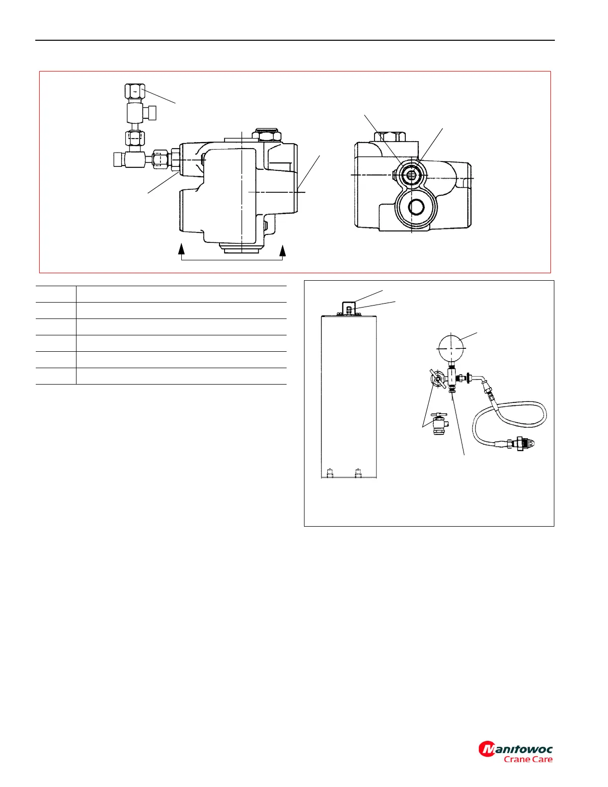
FIGURE 2-11
A
A
VIEW A-A
5
4
3
2
1
Item Description
1 Accumulator “A” port
2 Accumulator Pressure Test Port
3 Pressure “P” Port
4 Tank Port
5 Socket Head Screw Adjustment
FIGURE 2-12
Gas Valve Guard
Gas Valve
Gauge
Bleed Valve
Gas
Chuck
6659-6
Accumulator
Charging Assembly