2-28 Published 08-25-09, Control # 077-04
HYDRAULIC SYSTEM RT9130E SERVICE MANUAL
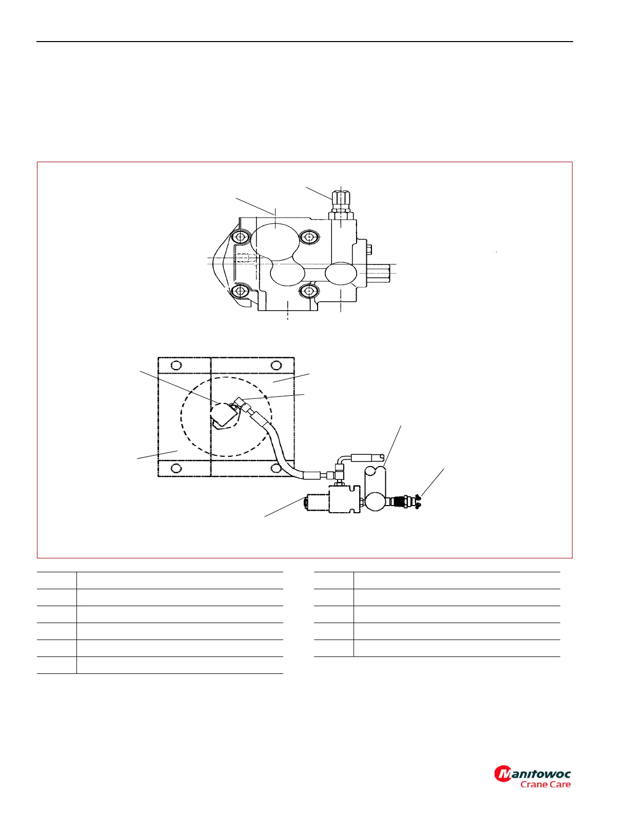
Procedure M - For Checking Oil Cooler
Circuit Relief Valve Pressure
1. Disconnect pressure hose at the Oil Cooler motor “Inlet”
port (Figure 2-16) and attach a pressure gauge.
2. Run the engine at idle (950 RPM), for 5 - 10 seconds
since the flow will be “hot looped”. Check the pressure.
Adjust the oil cooler relief valve in the pump on the side
of the engine (Figure 2-16) to 19.0
± 0.4 MPa (2700 ± 50
PSI). Remove pressure gauge and reconnect the
pressure line. If this step needs to be repeated, make
sure pump is Not Hot to touch. If it is, allow to cool
before proceeding.
Oil Cooler Pump (Rear View)
6699
FIGURE 2-16
Out Top Out
In In
Oil Cooler and Solenoid Valve
1
2
3
4
5
6
9
8
7
Item Description
1 Suction Port
2 Relief Valve
3 Hydraulic Oil Cooler
4 Inlet Port
5 Hydraulic Return Manifold
Item Description
6 Oil Cooler Temperature Switch #8 Screw
7 Oil Cooler Solenoid
8 Transmission Oil Cooler
9 Oil Cooler Motor