Published 08-25-09, Control # 077-04 3-3
RT9130E SERVICE MANUAL ELECTRICAL SYSTEM
crane. These fuses protect the Cummins engine electronic
control module (ECM) and carrier control module (CCM).
For machines with the retarder option, a 10A fuse in line 180
protects the retarder circuit parts.
Relays
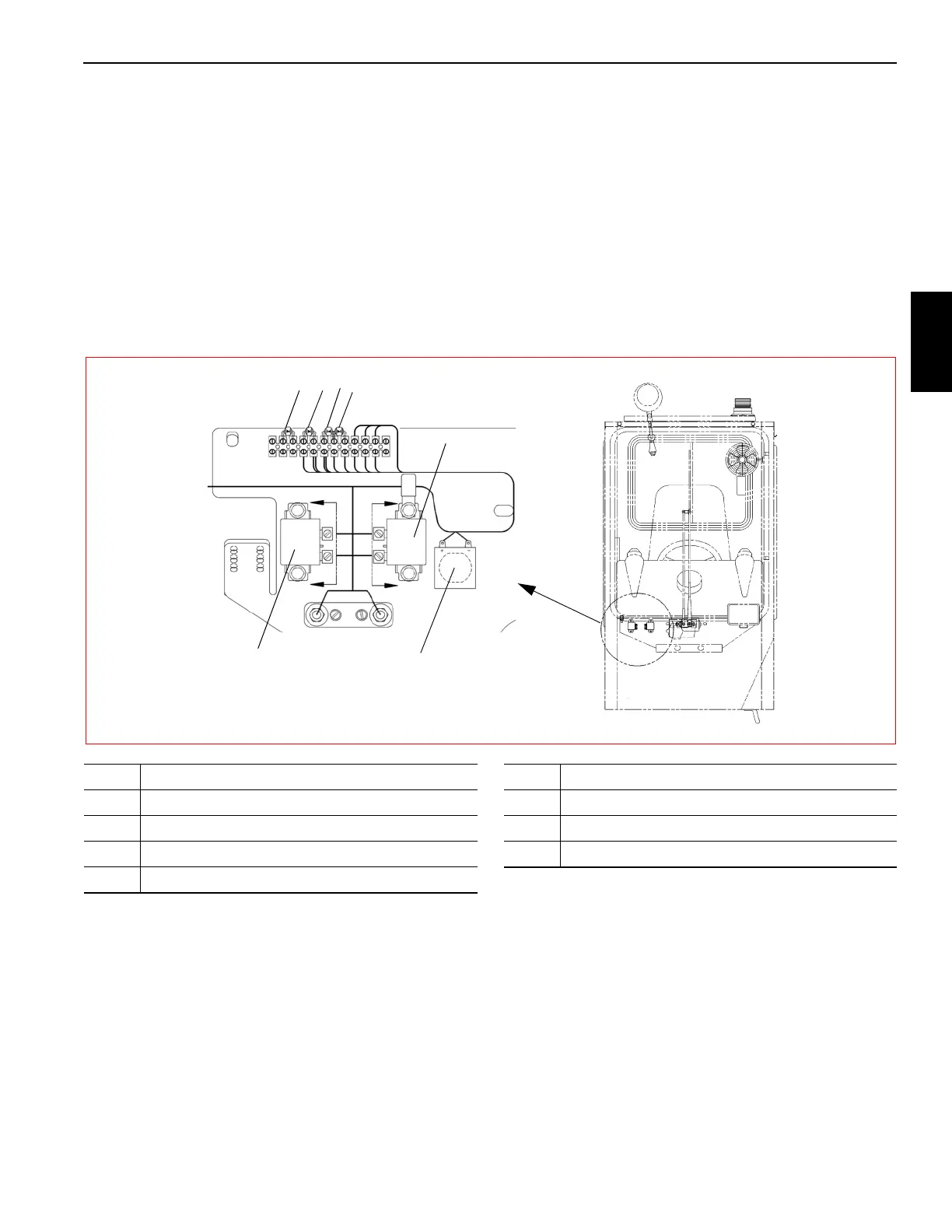
The relay panel (Figure 3-6) contains 2 relays (K1 and K2), a
terminal block with 3 or 4 or 5 diodes, and a buzzer. It is
located in front of the front console in the cab. Access is
gained by removing the front console cover.
The crane has 5 or 6 relays which control many of its
functions. In addition to relays K1 and K2 in the cab, relays
K601, K602, and K301 are located under the engine hood on
the engine relay panel on the left side of the engine
(Figure 3-7).
For the start relay coil to energize, the battery must be
connected. The coil of the start relay (K301) is energized
when the transmission is in neutral and the ignition switch is
at the START (2) position.
The coil of the accessory relays (K1 and K2) are energized
when the ignition switch is at the RUN (1) or ACC (3)
position.
For cranes with air conditioning, there is an optional AC Fans
relay (A/C).
FIGURE 3-6
Front of Cab
7
6
5
4
3
2
1
Item Description
1
ACC Relay 1 (K1)
2 ACC Relay 2 (K2)
3 Buzzer
4 Diode (D4)
Item Description
5 Diode (D5)
6 Diode (D6)
7 Diode (D7) Optional