3-2 Published 08-25-09, Control # 077-04
ELECTRICAL SYSTEM RT9130E SERVICE MANUAL
For a machine with the retarder option, there is a second pair
of batteries installed in a box on the left side of the crane
ahead of the fuel tank.
Fuse Panel
Most electrical circuits are protected by the components of
the relay panel assembly and the fuse panel.
The fuse panel (Figure 3-4) is located in front of the pin type
swing lock control tee handle and contains up to 20 fuses. To
gain access to the fuses, remove the snap-on cover. A decal
in the cover identities each fuse and its function.
Fuses 1, 2, 3, 4, 5, 6, 7 and 8 are energized when the battery
is connected. When the battery is connected and the ignition
switch is in the ignition (run) or accessory power position,
fuses 9 to 12 & fuse 20 are energized through ACC relay #1
(K1) and 13 to 19 are energized through ACC relay #2 (K2).
The following fuse assignments apply:
Table 3-1
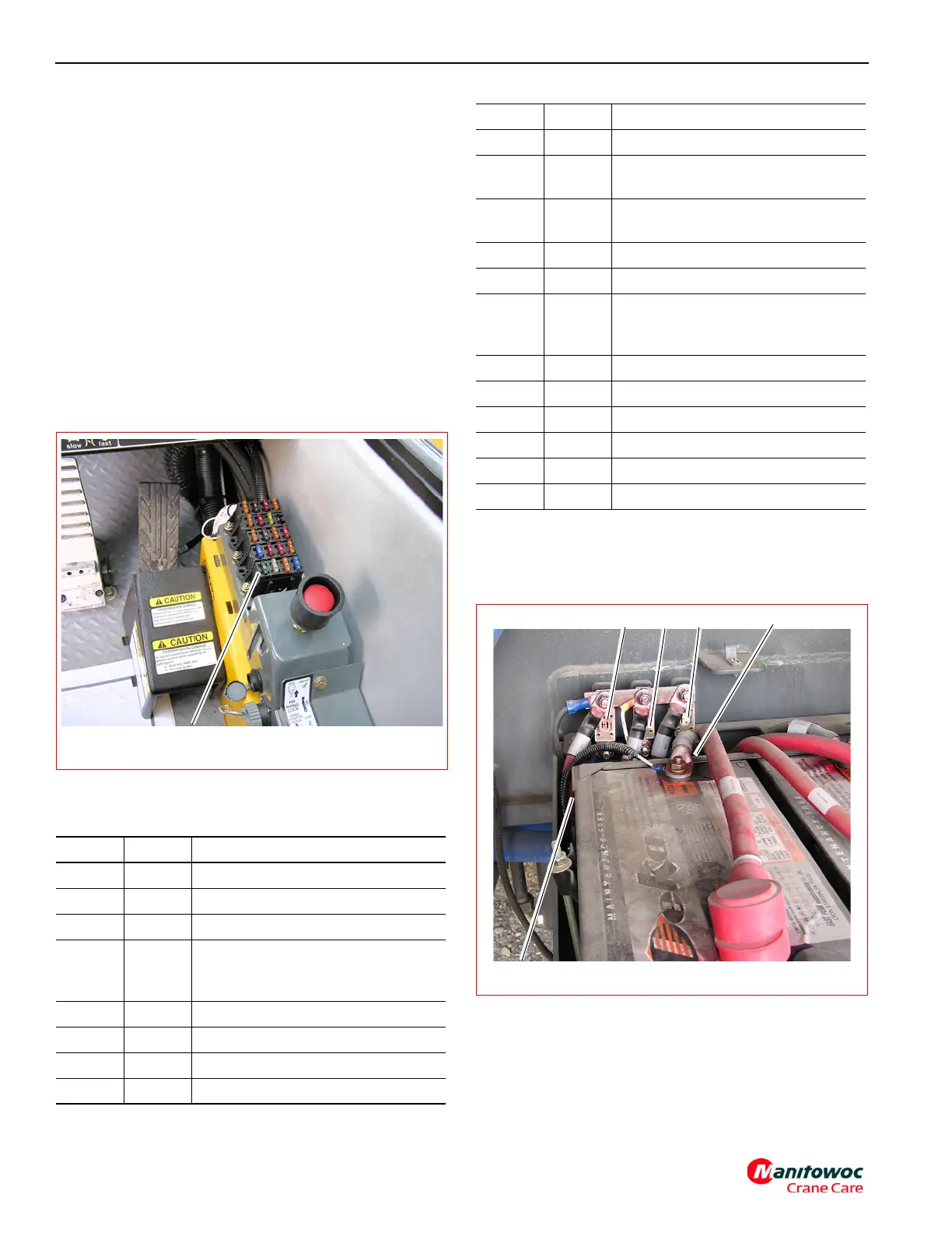
Fuses 51, 52 and 53 are inside the battery box compartment
located behind the fuel tank on the left side of the crane.
These 100-amp fuses protect the superstructure electrical
power system (Figure 3-5).
Fuse 54 and 55 are under the engine hood on the left side of
engine on frame rail. These 125-amp fuses protect the
engine grid heaters.
Fuses 56 (50A) and 57 (30 A) are located inside the battery
box compartment behind the batteries on the left side of
Fuse Amp Fuse Assignment
1 5 Work Light
2 10 Spare (8A max) (for DI radio)
3 7.5 Spotlight and Dome Lights
45
Headlights, Taillights, Brake Lights,
Turn Signal, Gage and Panel Lights
and Switch LED’
5--Spare
6 20 Superstructure Control Module
7 10 Boom Lights (option)
8 5 Ignition, Start and Accessories
FIGURE 3-4
7333-3
Fuse Panel
9 10 Windshield Wiper/Washer
10 5
Beacon Light, Drive Select,
Differential Lock, and Park Brake
11 7.5
Cab Circulation Fan and Skylight
Wiper
12 5 Defroster Fan
13 7.5 Swing Speed Solenoid
14 10
Indicator Lamps, Buzzer, Gauges,
Drive Enable, Outriggers, Rear
Steer Luffing Jib (option)
15 10 12 V Power Outlet (8A max)
16 15 LMI CPU Power
17 15 LMI CPU, Hoist Control
18 5 Hoist Rotation Indicators
19 25 Heater and A/C Fan
20 30 A/C Condenser Fan
Fuse Amp Fuse Assignment
FIGURE 3-5
7333-2
F51
F52
F53
F56 behind battery
F57 behind battery