BOOM RT9130E SERVICE MANUAL
4-50 Published 08-25-09, Control # 077-04
Installing/Removing Two-Stage Swingaway
Lattice Extension for Boom Extension
This section described the installation and removal of the
folded two-stage swingaway lattice extension.
You can also install the two-stage swingaway lattice
extension which has been folded in front of the other in front
of an 8 m section (e.g. when you are changing directly from
the 18 m two-stage swingaway lattice extension to a boom
extension) (Figure 4-13).
NOTE: An auxiliary crane must be used to install and
remove the two-stage swingaway lattice extension.
The securing pins (1) for the connection are in the holders on
the foot of the 11 m sections and are secured with retaining
pins (Figure 4-14).
Installation
• Sling the two-stage swingaway lattice extension onto an
auxiliary crane.
• Lift the two-stage swingaway lattice extension in front of
the 8 m section so that the bearing points (2) and (3)
align on both sides (Figure 4-14).
• Insert the securing pins on both sides into the bearing
points (2) and (3) (Figure 4-14).
• Secure all pins with retaining pins.
Removing
• Sling the two-stage swingaway lattice extension onto an
auxiliary crane.
• Lift the two-stage swingaway lattice extension until the
load has been relieved from the bearing points.
• Release the pins and knock them out of the bearing
points (2) and (3) on both sides (Figure 4-14).
• Insert the pins into the holders on the 11 m section and
secure them with retaining pins.
Hydraulic Connection On the Boom
Extension (If Unit Is Equipped With
Hydraulic Luffing Boom Extension)
The hydraulic connection is required for raising and lowering
the lattice extension. If the hydraulic connections for the
hose drum were separated on the left side, they have to be
re-established.
NOTE: The connections are made via quick couplings.
Half couplings which belong together are color
coded.
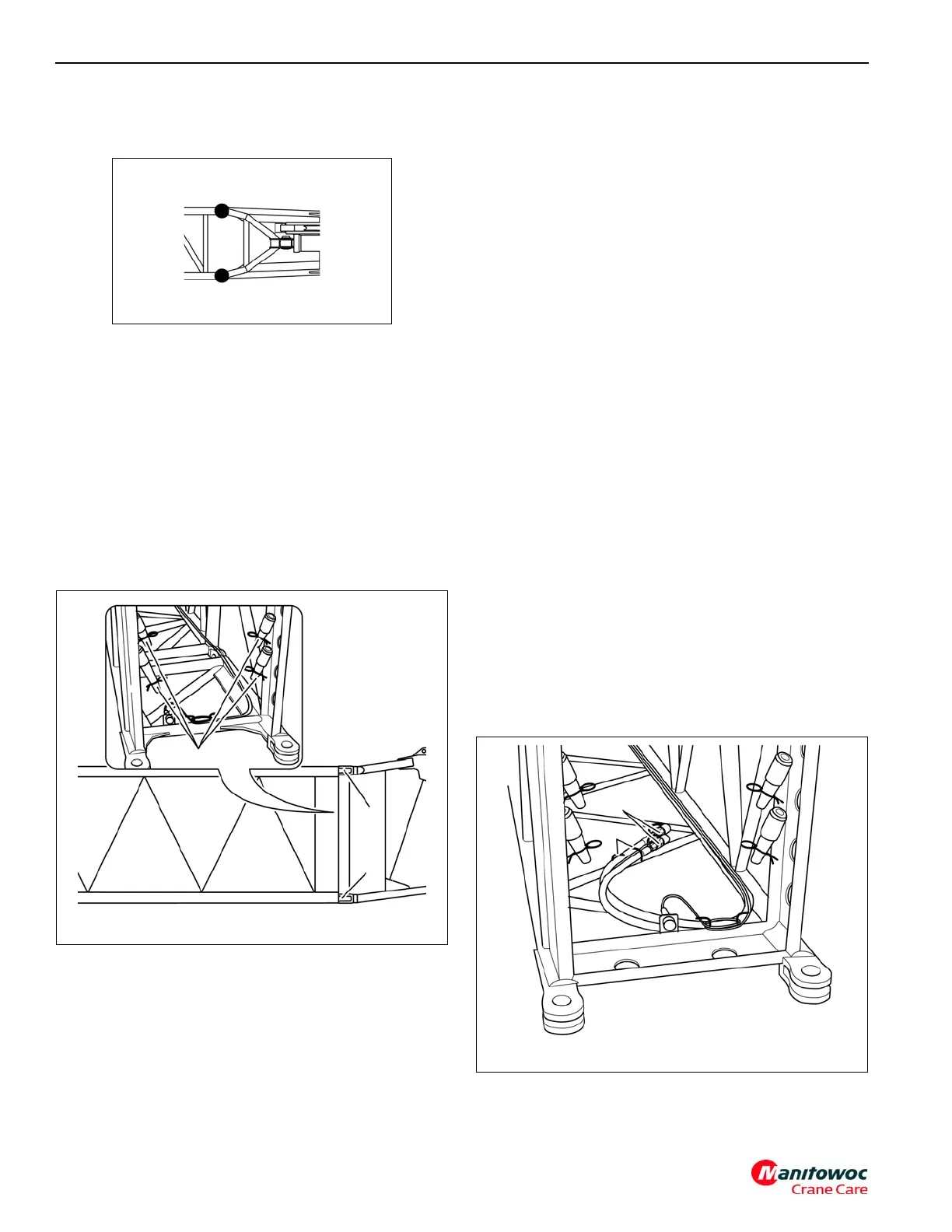
Connections On the 8 m Sections
At the rear of the 8 m sections there are two hydraulic hoses
(1) with quick couplings. These hydraulic hoses can be
connected on the main boom head or on a second 8 m
section (Figure 4-15)
For transportation, the hydraulic hoses are clamped in the
holders (2) (Figure 4-15).