6-12 Published 08-25-09, Control # 077-04
SWING SYSTEM RT9130E SERVICE MANUAL
Removal
1. Fully extend and set the outriggers enough to take up
the slack in the pads.
NOTE: Do not raise the machine on the outriggers.
2. Ensure the boom is in the travel position and the
turntable lock pin is engaged.
3. Elevate the boom slightly and shut down the engine.
4. Tag and disconnect the battery cables from the
batteries.
NOTE: The boom assembly weighs approximately 16,600
kg (36,610 pounds) without stowed boom
extension. Removal of the swingaway boom
extension will simplify boom removal, therefore, the
above weight is for the boom without the
swingaway boom extension attached. The lift
cylinder weighs approximately 1770 kg (3893
pounds).
5. Remove the boom and lift cylinder following the
procedures outlined in Section 4, BOOM.
NOTE: The counterweight/auxiliary hoist and structure
weighs approximately 20,400 kg (45,000 pounds).
6. Remove the counterweight and auxiliary hoist following
procedures outlined in Section 4 of the Operator’s
Manual.
7. Tag and disconnect all water and oil lines from the
bottom of the swivel. Cap or plug all lines and openings.
8. Locate the connectors and ground wire that joins the
swivel wiring harness to the receptacles and ground
stud on the carrier.
9. Disconnect the swivel wiring harness connectors from
the carrier wiring receptacles. Remove the ground wire
from the ground stud.
10. Remove the clamp securing the swivel wiring harness to
the retainer plate on the bottom of the hydraulic swivel
assembly.
11. Coil the wiring harness and secure it to the swivel to
prevent damage to the harness during turntable
removal.
12. On the bottom of the hydraulic swivel, bend the retainer
tabs away from the bolt heads. Remove the eight bolts
and four bolt retainers securing the two retainer plates to
the spool. Remove the retainer plates from the spool
and the lugs on the carrier frame.
Grove U.S L.L.C.
Customer Support
1565 Buchanan Trail East
Shady Grove, PA 17256
Phone: (717) 597-8121
Fax: (717) 593-5929
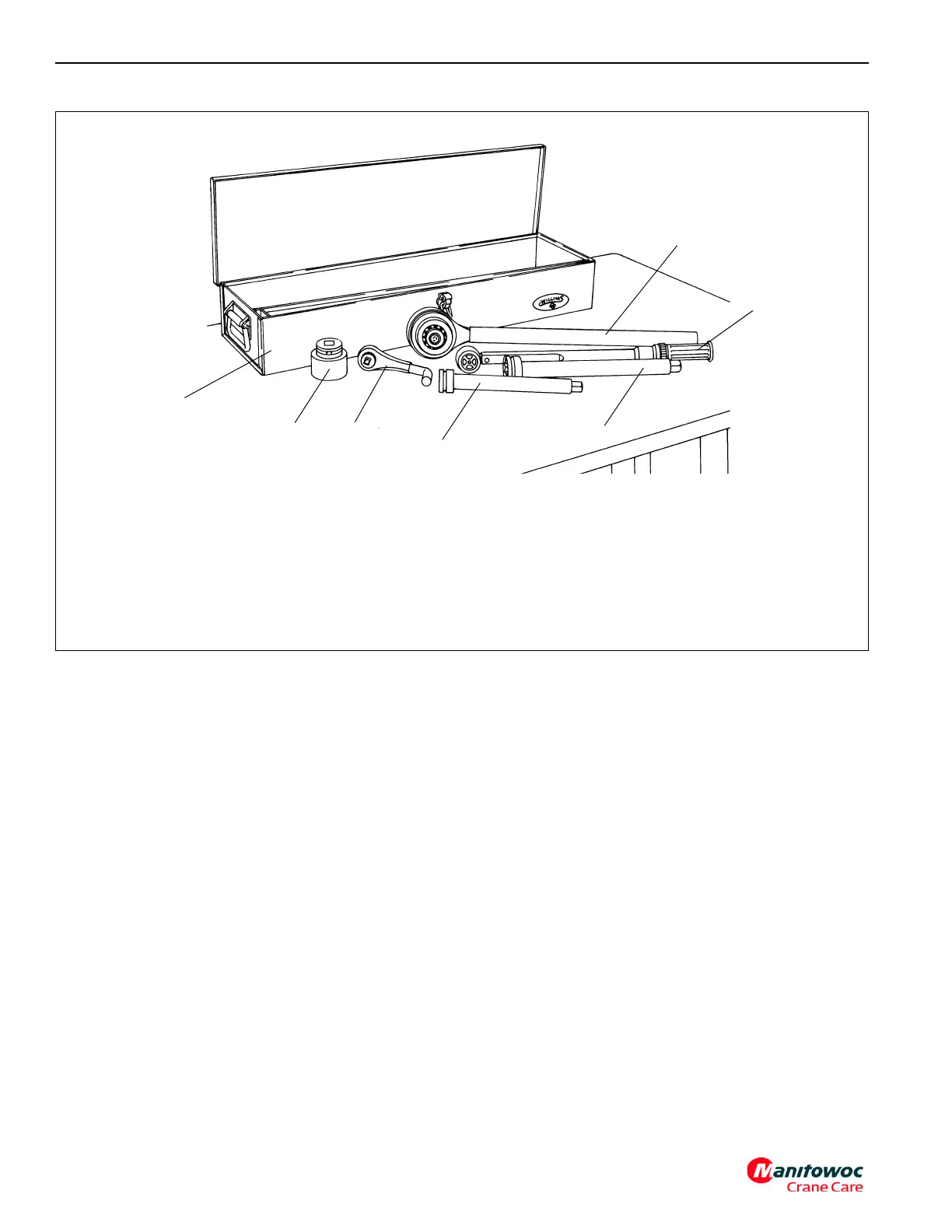
Description
1. 1 13/16 “Socket 3/4” Drive
2. 4 to 1 Torque Multiplier (1/2” Input 3/4” Output)
3. Backlash Adapter
4. 1/2” Drive Torque Wrench
5. 10” Extension 3/4” Drive
6. 13“Extension 3/4” Drive
7. Tool Box (Optional)
Grove Part Number
9-999-101988
9-999-100134
9-999-100141
9-999-100136
9-999-100138
9-999-100137
9-999-100146
Quantity Required
1
1
1
1
A/R
A/R
1
6633
FIGURE 6-3
Orders for special tools
shall be referred to:
7
1
5
3
2
4
6